Any engine repair should begin with the correct diagnosis, which may in fact reveal that a mechanical repair is not required. It would be unfortunate to perform a significant mechanical repair like an engine overhaul, only to determine that the real malfunction was in another system. Also, make sure you diagnose and repair the real problem and not just focus on the results of the problem. In many cases something other than the engine malfunctioned and in turn caused the engine to fail. This problem must be addressed before the vehicle leaves or the engine will only fail again. It doesn't make any sense to overhaul an engine that overheated without repairing the cause of the cooling system failure. Proper engine diagnosis begins with listening to the customer's complaint. Then, visually inspect the engine assembly and listen for abnormal engine noise. If the engine is using excessive amounts of oil or coolant, determine the cause and check the exhaust color and odor. Finally, perform vacuum, compression, cylinder leakage and cylinder balance tests in order to determine your course of action. The first step in diagnosis is talking to the customer. Get a detailed description of what happens and under what conditions it happens, then verify the information. Conduct a road test if possible. Before road testing the vehicle, visually inspect the engine for obvious problems such as:
If the engine won't start or is hard to start, you'll have to determine if the reason is due to a cranking system, ignition system, fuel system or engine mechanical problem. If the engine won't crank, check the battery terminal connections and make sure they are clean and tight. If the battery has removable caps, check the electrolyte level and specific gravity. On sealed maintenance-free batteries, check the color of the built-in charge indicator. Check the open circuit voltage using a voltmeter and charge the battery if necessary. Load test the battery to determine if it can provide sufficient current to the starter. If the battery tests good and the engine still won't crank, check the cables, wiring and connections in the starter circuit. Make sure the solenoid is functioning and the starter is properly mounted. Perform a starter current draw test. Current draw that is greater than specification could be caused by a bad starter or a binding mechanical assembly. Remove the spark plugs and then attempt to turn the engine by hand. If the engine can be turned by hand using suitable tools at the flywheel or crank- shaft balancer, then the problem is with the starter. If the engine cannot be turned by hand, it may be seized or have broken internal components. If the engine cranks, but seems to crank too easily, the timing belt or chain may have broken or jumped time. Rotate the crankshaft by hand while watching for distributor rotor or camshaft movement. If the rotor or camshaft do not move when the crankshaft is turned, the belt or chain is broken. If they turn when the crankshaft is turned, bring the piston in cylinder No. 1 to TDC (Top Dead Center) on the compression stroke and verify that the valve timing is correct. A broken timing belt or timing chain, or incorrect valve timing caused by a belt or chain that has jumped time, can result in valve to piston contact on some engines. If the cam drive system and valve timing are OK and the engine cranks normally but won't start, check for spark and adequate fuel delivery. Check for spark at the park plug wires using a spark tester. If the spark plugs do not fire, first determine in which part of the ignition circuit the fault lies. Disconnect the coil wire from he distributor cap and check for a good spark with the spark rester while cranking the engine. If there is a good spark, the problem is in the ignition secondary circuit (distributor cap, rotor, wires and plugs). If there is no spark or a weak spark, the problem is in the ignition primary circuit.Check the ignition module and coil. If they are OK, continue testing component wiring and connections back through the primary circuit. Check the fuel by disconnecting the fuel pressure feed line and inserting it into a graduated container. On systems with mechanical fuel pumps, crank the starter motor. On systems with electric fuel pumps, you usually must operate the pump with a jumper wire for a specified period.First, you should be able to hear the electric fuel pump running in the tank. If not, the pump must be removed for further inspection. If the electric pump runs, it should flow at least a half-pint of fuel in 30 seconds. If not, before condemning the pump, check the external and in-tank fuel filters and the fuel lines for restriction. Also, perform a voltage drop test on the power and ground circuits to the pump. At this point, the engine should be cranking properly, have spark and adequate fuel delivery. If the engine still does nor start, further diagnosis of the fuel and electronic engine control system are needed. However, an engine that cranks, has spark and fuel might also not start because of a severe exhaust restriction.Connect a vacuum gauge to the intake manifold and crank the engine. A good engine should have a steady 3-5 in. Hg vacuum while cranking. If there is zero vacuum while cranking, this could be an indication of blockage in the exhaust system.Disconnect the exhaust pipe(s) at the manifold(s) and try to start the engine.
Since the fuel system is under pressure when the engine is running (and on fuel injection systems, remains under pressure, even after the engine has been turned off), the source of a fuel leak is usually not difficult to find. Fuel can leak from damaged lines or hoses or from loose fittings. Inspect hoses for cracks and swelling and inspect the condition and security of hose clamps. Inspect fuel lines for cracks, corrosion and damage from abrasion. Make sure all fittings are properly installed and tightened. A leak from a fitting that is tight may be caused by a damaged O-ring. On vehicles with fuel injection, components like the fuel pressure regulator can also be the source of a fuel leak.
Oil leaks are most often caused by hardened or worn out seals and gaskets, or leaking oil pressure sending units: However, engine oil leaks can also be caused by something technicians often overlook - excessive crankcase pressure, which can be caused by worn rings or excessive cylinder wall clearances. These problems allow an unusual amount of combustion blow-by gases to enter the crankcase, where the gases can push oil past seals and gaskets that are in good condition. The key here is to look for related symptoms, such as spark plugs that are oil-fouled or show signs of oil deposits. Look for the telltale blue-gray or gray-white exhaust smoke of an oil-burner. Excessive crankcase pressure can also build up in a perfectly good engine if the crankcase ventilation system isn't working properly. Remember that fresh air must be able to enter the crank-case. This means that the crank-case breather filter must be clean and the related plumbing must be unobstructed. It also means that the PCV valve must work correctly and its plumbing must be clean and in good condition. At idle, a substantial amount of air enters the PCV valve. If you pull the PCV valve out of its grommet with the engine idling, you should feel a strong suction at the valve's inlet. Many systems use a PCV orifice in place of the PCV valve. If the oil is not changed on a regular basis, this system will plug up. Some systems may have screens that can be removed and cleaned. To find the source of an oil leak, bring the engine to normal operating temperature and then park the vehicle over a large piece of paper or old sheet. Wait several minutes, and then check for dripping fluids. Of course, engine oil may not be the only fluid leaking from the vehicle, so you'll need to become familiar with the color, feel and smell of different fluids. Engine oil will be brown, dark brown or black and feel slippery. Automatic transmission fluid will be red or dark brown and smell differently than engine oil. Antifreeze can be green, orange or rust colored and, while slippery, will have a different feel than engine oil. Power steering fluid can be red or clear and will feel like transmission fluid. A clear or dark brown fluid that is significantly less slippery than engine oil is probably brake fluid or hydraulic clutch fluid. Check for leaks at sealing surface areas, fittings and sending units. If the source of the leak cannot be found, thoroughly clean the engine and surrounding components and apply powder to the suspected leak area. Operate the vehicle for several miles at normal operating temperature and again check for leaks, which will be indicated by discolorations in the powder. For hard to find oil leaks, add a fluorescent dye to the engine oil that is visible with a black light. Run the engine for a while and then pass the light around the engine. The dye should pinpoint the source of the leak.
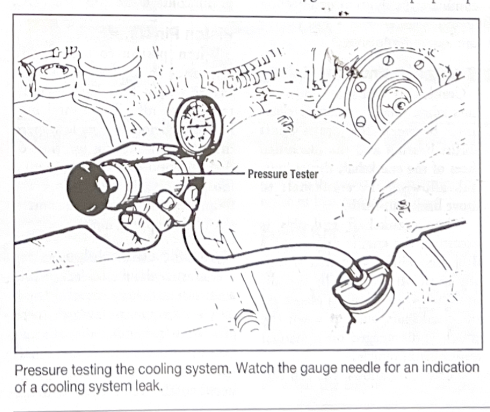
Visually inspect for coolant leaks at the radiator and heater hoses, water pump radiator, intake maniforld, sensort fittings, water control valves and heater core. Attach a suitable pressure tester to the coolant filler neck and apply pressure equal to the pressure rating marked on the radiator cap (make sure the cap is the correct one for the vehicle!). The pressure should remain at that level if there are no leaks in the cooling system. If the pressure drops, check for leaks in the same areas.

External coolant leaks are relatively easy to find. But, what if you pressurize the cooling systems with a cooling system pressure tester, the pressure drops and no coolant appears outside the enginge? This indicates that the coolant leak is inside the engine and is most likely caaused by a defective intake manifold or timing cover gasket, blown head gasket, cracked cylinder head or cracked block. Inspect the engine oil for sings of coolant; if it is thick and milky, that's a dead giveaway. Symptoms will vary depending upon the severity of an internal coolant leak. When coolant leaks into a cylninder, it may create white exhaust smoke and a somewhat sweet antifreeze odor in the exhaust. It may also cause misfiring, especially when the engine is cold. Unfortantely, catalytic converters can mask small coolant leak symptoms. The converter super-heats the coolant into such a fine vapor that it is not noticeable. A coolant leak can also damage oxygen sensors. If a coolant leak has been confirmed and repaired, always test the oxygen sensor for proper operation, or divibility symptoms may remain. If coolant is leaking into a cylinder, combustion gases will also be able to escape into the cooling system. When combustion has escapes into the cooling system, it can cause big air bubbles to appear in the radiator coolant when the engine is running. It can also pressurize the coolant recovery reservoir. One common internal coolant leak detection procedure uses a chemical that is sensitive to combustion gas. With the engine running, place a vial of the chemical over the radiaotr neck and draw vapors from the top of the radiator into the vial. If the chemical changes color, you know that combustion gases are leaking into the coolant system. Another way to detect combustion gas is to carefully hold the exhaust analyzer probe over the neck of the radiator. Do not allow the probe to draw in coolant. Cup a clean cloth or a plastic bag with a hole for the probe over the radiator neck. If combustion gas is entering the coolant, you'll see a reading on the exhaust analyzer. Sometimes when you disable cylinders, the bubbles appearing in the radiator will diminish when you eliminate the cylinder that has the coolant leak. Disabling the leaking cylinder may also reveal little or no rpm drop compared to other cylinders. Remember, in closed loop the computer may adjust idle and mixture faster than you can hear or see an rpm change. Closely examine the spark plugs. When combustion heat evaporates the leaking coolant, it not only creates white exhaust smoke it also tends to clean the porcelain insulator that surrounds the plugs center electrode. If the radiator is cool enough to do so, remove the radiator cap. Remove all the spark plugs. Then perform a leak-down test on the cylinder with the unusually clean looking spark plug. If pumping air into that cylinder produces bubbles in the radiator coolant, you know that the leak is in that cylinder. If you also find that air escapes from an adjacent cylinder, you know that the head gasket has blown out between those two cylinders and has caused both a compression leak and a coolant leak. In cases where disabling cylinders or inspecting the spark plugs faul to point to a particular cylinder, perfrom a leak-down test on each cylinder. After you have pinpointed the leaking cylinder and have dissassembled the engine, always inspect both the block and the head for cracks and warpage.
Generally, noises are caused by too much clearance between parts or loss of oil pressure. The following common engine noises can be caused by any these parts:
Crackshaft end-play noise occurs when there is excessive clearance between the crank-shaft thrust bearing and the machined faces of the crankshaft thrust journal, allowing the crankshaft to move back-and-forth. When crackshaft end-play is excessive, the engine may make a deep knocking sound that is usially most obvious at idle bit dimisnishes when a load is placed on the crackshaft, such as when the clutch is disengaged on a manual transmission vehicle. Where space allows, you can verify excessive crankshaft end-play by fitting a dial indicator to the tip of the crankshaft. Using a prybar, carefully pry the crank-shaft back and forth and note the reading on the dial indicator. Compare the reading with specifications.
Excessive piston-to-wall clearance can cause piston slap. This is caused by side-to-side movement of the piston withing the cylinder bore, and sounds like a dull or muffled metallic rattle at idle or during light engine loads. Very faint piston slap my disappear after the engine warms up and the piston expands. In this case, the piston-to-wall clearance usually isn't severe enough to worry about. However, piston slap that continues after the engine warms up should be corrected. Note that unlike a connecting rod bearing noise, piston slap does not quiet down and may in fact grow louder when you eliminate ignition or fuel injection to that cylinder. A knocking noise can be caused by excessive carbon buildup in the combustion chamber where the piston contacts the carbon at TDC.
A noisy hydraulic lifter is usually a consistent ticking sound that occurs at a frequency slower than engine rpm (remember that the valvetrain operates at half crankshaft rpm). Try sliding a feeler guage between valve stem and the rocker arm. If this eliminates the ticking, it confirms that there is excessive clearance in the valvetrain. With the engine running, you can also press down on the pushrod end of each rocker arm with a peice of wood or a hammer handle. If this stops or reduces the ticking, you have pinpointed the faulty lifter. Always check valve adjustment and inspect valvetrain parts for wear or damage. Worn valvetrain parts can mimic the noise of bad hydraulic lifters.

Examples of normal combustion (top), preignition (center) and detonation (bottom)
Spark Knock
Spark knock, which is caused by two kinds of abnormal, uncontrolled combustion, sounds like a metallic pinging or ringing noise. You may hear spark knock when the engine is under heavy load and being run at too low an rpm, or when the engine is accelerating. An engine that is running too hot and/or has excessive combustion deposits can also suffer from spark knock.
Preignition spark knock occurs when a hot piece of carbon or metal inside the combustion chamber prematurely ignites the air/fuel mixture. Then the spark plug ignites the remaining mixture at the normal time. When the two portions of burning mixutre meet each other inside the combustion chamber, there is a sudden and abnormal rise in cylinder pressure, which causes engine vibration in that cylinder.
Detonation spark knock is primarily caused by fuel with too low an octate rating for the eninge, ignition timing that is too far advanced, high engine operating temperature or excessive carbon buildup in the combustion chamber. If the octane rating is too low for the engine, it basically means that the fuel will burn too quickly. When detonation occurs, the spark fires, the mixture begins burning, and pressure in the cylinder begins rising. But the rise in normal pressure causes part of the air/fuel mixture elsewhere in the combustion chamber to self-ignite. Then the two flame fronts collide as in the preignitio situation.
Both preignistion and detonation can cause damage to pistons and spark plugs.
Most vehicles have knock sensor to adjust timing as neeed to avoid damage however, excessive spark knock may be a sign of engine control problems. Before any major engine tear dowm, check the engine control system. EGR (Ehxaust Gas Recirculation) operation, knock control, coolant level, or any number of engine sensors or solenoids can cause spark knock. Asking the customer how long the engine has made this noise is the best way to determine how much damage may have occured.
The three common causes of excessive oil consuption are oil leaks, valve guide/valve seal problems, and piston ring problems.
When an engine is using oil, inspect it visually for serious oil leaks first. Check the crackcase ventilation systesm as a matter of routine. If you don't, the oil leaks may reappear in spite of the new seals and gaskets you install.
A Careful road test can be a critical diagnostic step in determning the cause of the oil burning. Note when the oil smoke is most intense. Typically, bad piston rings will make engine smoke worse when it is accelerating -- especially after it has been idling for a long time.
When a vehicle suffers from worn valve guides and/or bad valve stem seals, you'll see exhuast smoke during deceleration. The high intake vacuum that occurs during deceleration draws the oil through the worn guides or seals. Remember, the catalytic converter will super-heat the oil and reduce some of the smoke that would have been seen on pre-converter modles.
Reading the spark plugs can also confrim your diagnosis. When the excess oil is coming from the valve guide, the oil deposits on the spark plug tend to accumulate only on one side of the spark plug. When the excess oil is coming from the rings, the deposits on the spark plug ten to accumulate around the entire spark plug.
Before you blame either the valve guides or the valve seals for an oil consumption problem, verify that all of the oil return holes are clean. If oil cannot drain freely back into the crankcase, it can accumulate in the head and be drawn by vacuum into the combustion chamber, increasing oil consumption and causing exhaust smoke. Valve stem seals are designed to keep normal amounts of lubricating oil from entering the combustion chamber, but seldom work well when submerged in oil.
Properly disable the ignition and fuel systems. Connect an ammeter to the starting circuit and a vacuum gauge to the intake manifold. Crank the engine, listen to the cranking rhythm, and watch your instruments.
On a good engine, the cranking speed and cranking rhythm will sound crisp and consisten. There will be no 'pauses' or uneven rhythms, suggesting binding or differing compression values. The ammeter will stabalize at a consistent current draw reading that's withing specifications. The vacuum guage will read a fairly steady 3 to 5 in. Hg or more.
The better the rings and valves are sealing, the stronger cranking vacuum wil be. All things being equal, the following are true:
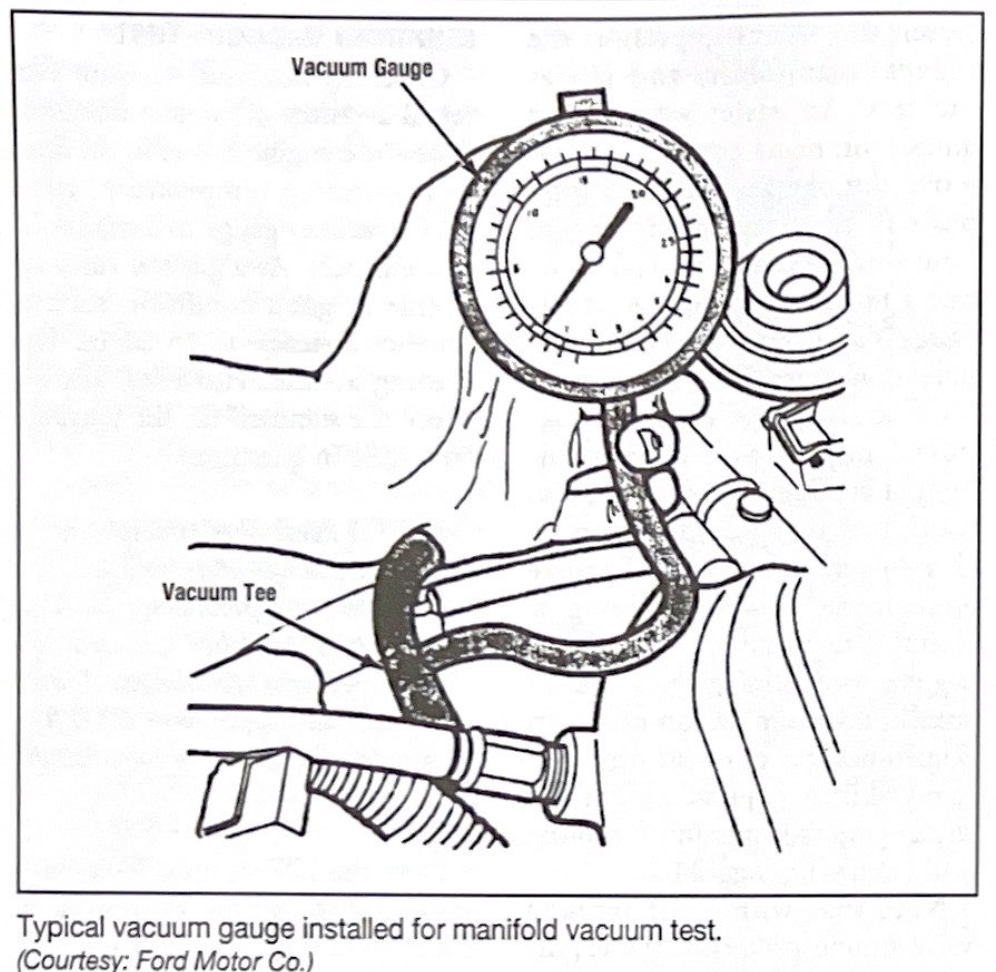
Typical vacuum guage installed for manifold vacuum test.
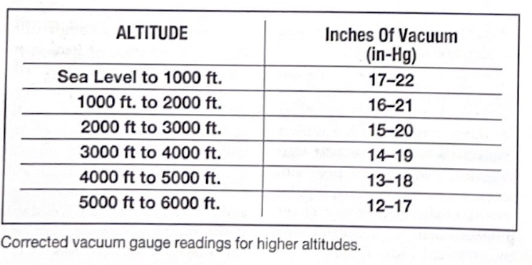
Connected vacuum guage readins for higer altitudes.
With a cylinder power balance test, you can compare the power output of all the engine's cylinders. Some technicians call it a power contribution test because it indicates how much power each cylinder contributes to the engine. The power balance test is an important technique for solving rough idle complaints.
To perfrom this test, let the engine idle and short out the ignition to each cylinder, one cylinder at a time. Some technicians also short cylinders at 1500 rpm and compare the results with those of the idle test. You can use an engine analyzer or a cylinder-shorting device to do this test safely. When in doubt, always refer to the manufacturer's recommended procedures for power balance tests. Many Ford products do this test during the Key On Engine Running test turning off injectors.
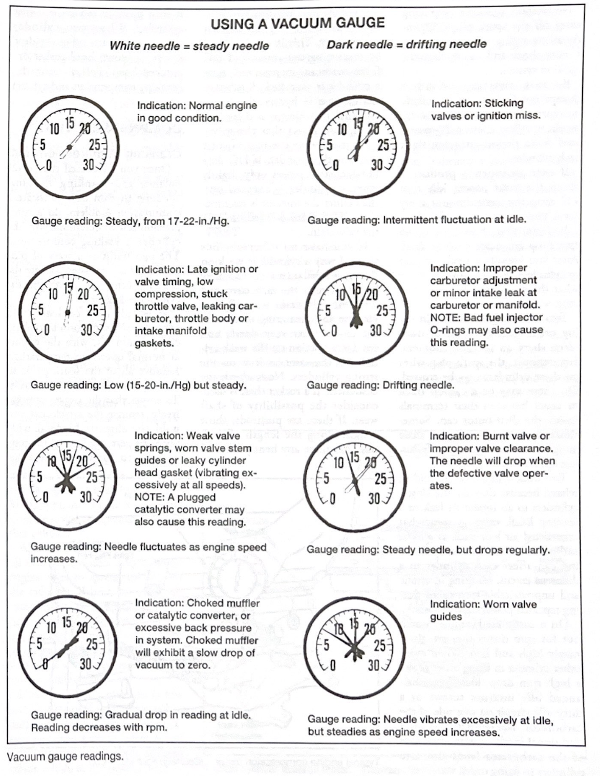
Vacuum gauge readings.
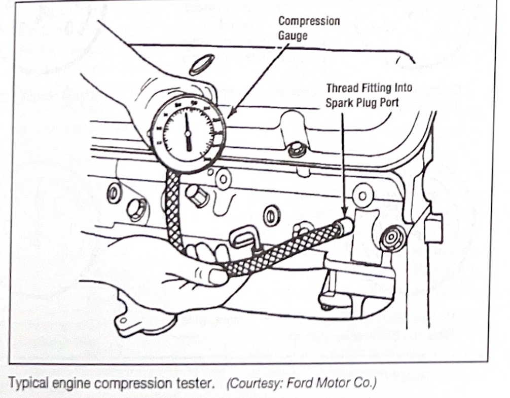
Typical engine compression tester.
Once you have used the power balance and cranking vacuum/cranking rhythm tests to locate a compression problem, do a compression test to determine why the clylinder is leaking compression. The two traditional ways of pinpointing a compression leak are the cranking compression test and the cylinder leakage test.
To get the most consistent and accurate results, perfrom a cranking compression test with the engine at normal operating temperature. Remove all of the spark plugs so the engine will crank more easily. To ensure that the engine breathes freely, remove the air cleaner and hold the throttle blade(s) wide open. Be sure the battery is strong enought to maintain the same cranking speed throughout the test. Use a battery charger if the battery is questionable.
Where necessary, ground the coil wire to prevent it from arcing. Also, disable fuel injection systems so they don't spray fuel during the compression test. Service manuals usually list compression pressure specifications as well as allowable deviations from them.
Connect the compression guage to the cylinder being tested, crank the engine through four compression strokes (four puffs on the compression guage) and note how the guage responds. Usually, cranking each cylinder through four compression strokes will give you an accurate compression reading. Pay close attention to how the guage responds to each puff. A healthy cylinder usually builds most of its pressure on the first stroke and contiunes building to a good compression reading.
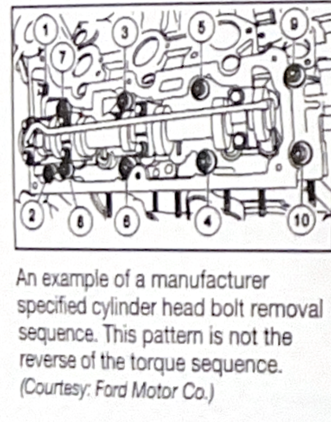
An example of a manufacturer specified cylinder head bolt removal sequence. This pattern is not the reverse of the torque sequence.
The only specialty tools needed for disassembly are a valve spring compressor and a valve stem height guage.
Before you take anything apart, carefully inspect the head for obvious damage such as a broken casting, cracks, stripped threads, broken studs, etc., and for missing components. Serious damage like a crack or broken casting may make the head unsuitable for reconditioning. Also look for any markings indicating the head had been milled or fitted with a cam with oversized journals.
First remove all components necessary to gain access to the valve components as well as components that are not integral to the cylinder head. Identify the locations of all parts, prior to removal for assembly reference, Photographs, drawing, tags, etc. are methods that can be used for reference.
Remove all housings, coversm sensors, timing and oil pump drive components. These parts cannot be left on the cylinder head as they could be damaged during the reconditioning process. Inspect all parts for wear and damage as they are removed.
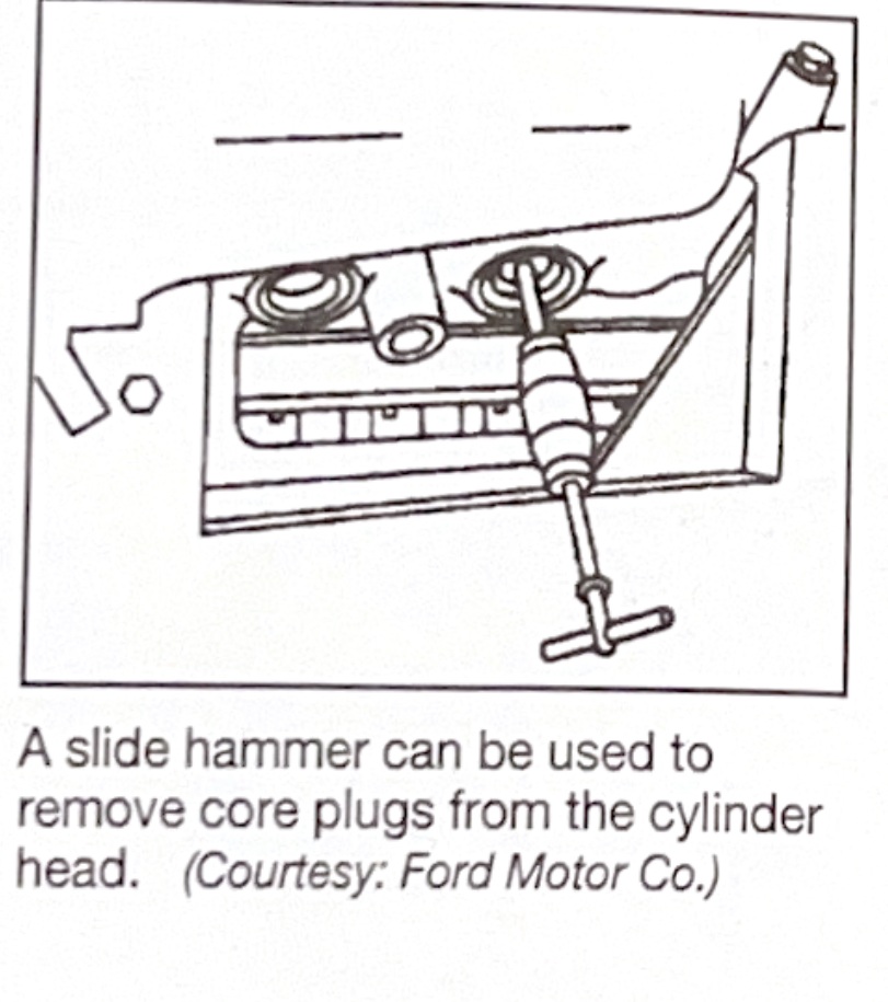
A slide hammer can be used to remove core plugs from the cylinder head.

Valvetrain components develop wear patterns, so all parts should be kept in order as they are removed. Inspect all components as they are removed for signs of obious wear and damage. Even if wear to thse parts is found to be withing specification, they should still be reassembled intheir original order.
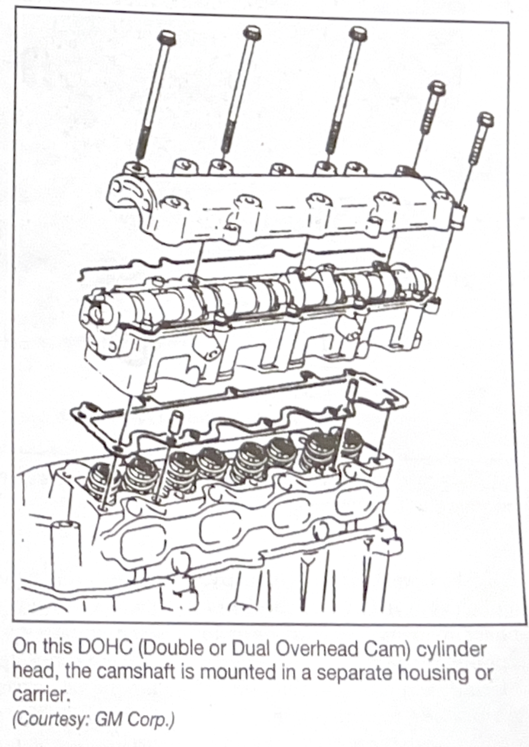
On this DOCH(Double or Dual Overhead Cam) cylinder head, the camshaft is mounted in separate housing or carrier.
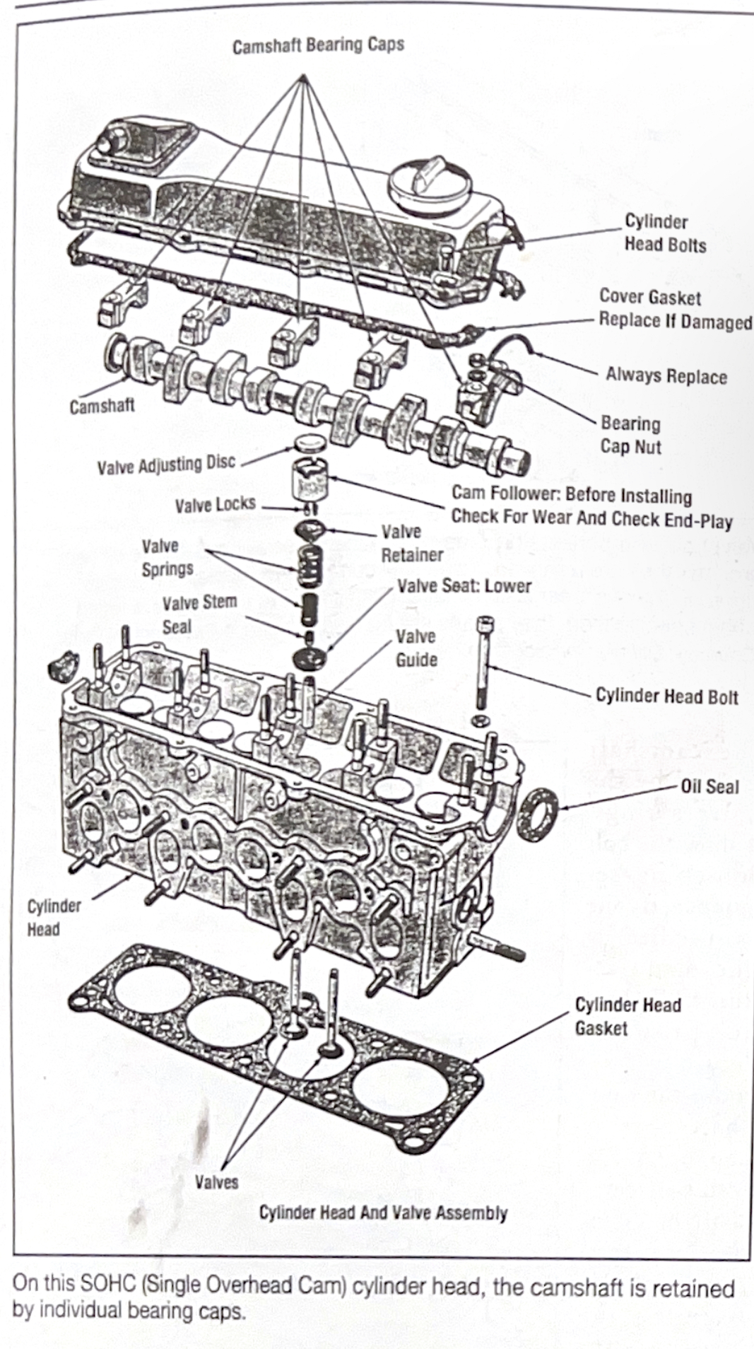
On this SOHC (Single Overhead Cam) cylinder head, the camshaft is retained by individual bearing caps.
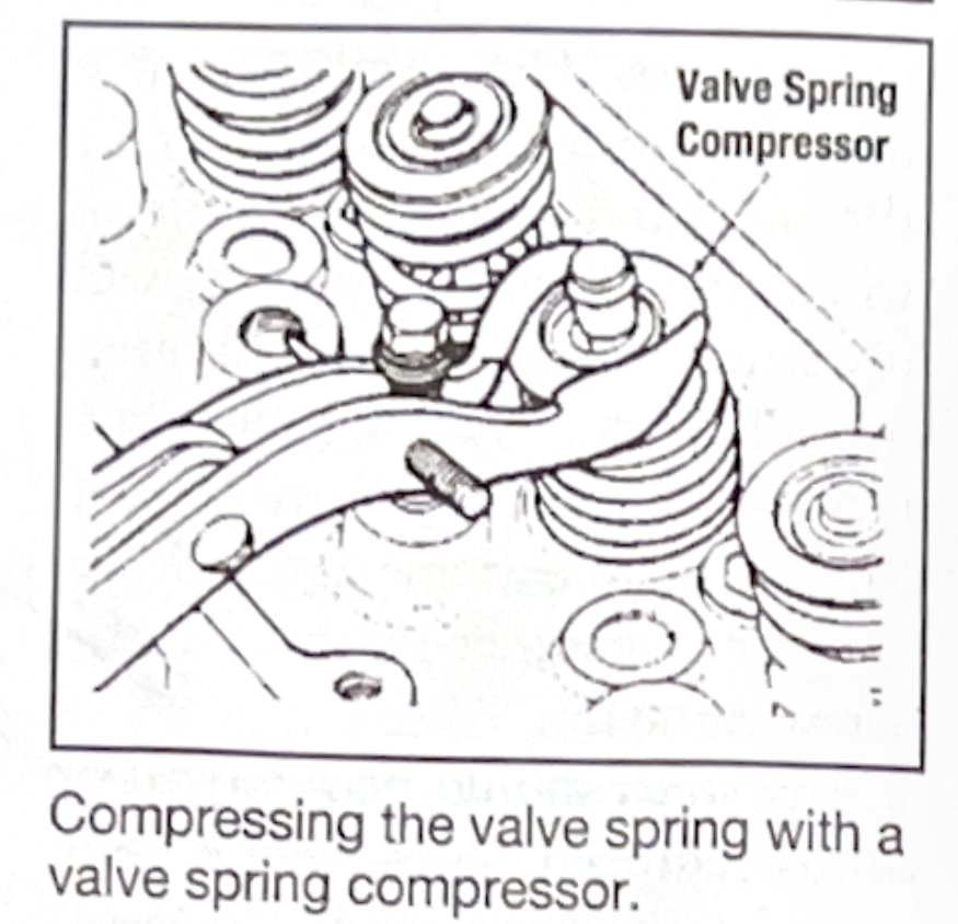
Compressing the valve spring with a valve spring compressor.
The method of cleaning selected should remove all grease, carbon and dirt from the head and valve components without damaging the metal. Caustic soda dissolves aluminum. When cleaning aluminum, the chemicals in a hot tank, cold tank, or jet spray washer must be aluminum safe.
Thermal cleaning in an oven will bake off the grease and oil in the head leaving behind a dry powdery ash residue. This residue is removed by washing, airless shot blasting or glass beading. With aluminum heads, baking temperatures should generally be reduced from the usual 650-750°F (344-399°C) down to 400-450°F (205-232°C). Higher temperatures can cause valve seats to fall out. Also, a few heads are impregnated with resin at the factory to seal against porosity leaks. The resin will be burned out by excessive temperatures.
When cleaning heads with an airless shot blaster or glass beads, all of the blast material must be removed from the head cavities after cleaning. Glass or steel cleaning media can cause severe engine damage. A tumbler is commonly used for this purpose. Steel shot is too abrasive to use on soft aluminum heads. An alternative is to use aluminum shot. It's softer and less apt to cause damage if a particle finds its way into the engine. Glass beading can be used on aluminum to remove carbon and hard, dry deposits. Crushed walnut shells and plastic media are other alternative soft cleaning materials.
Note:Glass beads are especially prone to sticking to wet surfaces inside oil galleries. This method should not be used on an aluminum head that is not completely dry.
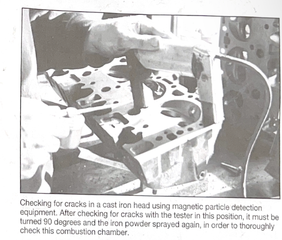
Checking for cracks in a cast iron head using magnetic particle detection equipment. After checking for cracks with the tester in this position, it must be turned 90 degrees and the iron powder sprayed again, in order to thoroughly check this combustion chamber.
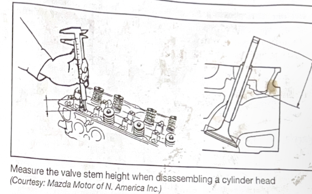
Measure the valve stem height when disassembling a cylinder head.
After the head has been thoroughly cleaned, inspect it for cracks. Cracks are generally caused by thermal stress, but sometimes result from casting imperfections. The most common places where cracks form are between the valve seats, in the vicinity of the spark plug hole, in exhaust ports, near the valve guides, and uder the spring seats. When cracks extend into the cooling jacket, they often leak coolant into the combustion chamber. Due to the breakdown in lubrication, ring, cylinder, and bearing damage usually results. Cracks that are not leaking coolant are still considered a potential problem because cracks tend to grow. They may begin to leak eventually.
Crack inspection can be done in several ways: using fluorescent dyes, magnent crack detection equipment, pressure testing or vacuum testing. Magnetic crack detection testing. Magnetic crack detection can only be done on ferrous (iron and steel) parts. Dye penetrants can be used on aluminum castings since they are not magnetic. Pressure testing can vacuum testing can be used to check for cracks and porosity in iron and aluminum heads.
Magnetic particle detectionis a fast and easy way to find hairline cracks in cast iron heads. The magnetic field created by the tester attracts iron powder applied to the head. A secondary magnetic field is created at the location of a crack. Additional power accumulates around this field, outlinning the crack. This technique will not reveal a crack that is parallel to the magnetic field. A second magnetic check is made by turning the tester 90 degrees. This can catch any cracks that might have been missed on the first try. It is difficult to find internal cracks in water jackets and ports with this technique.
Dye penetrant is a method of crack detection that can be used on aluminum. Dye is sprayed on the surface and allowed to dry. Then the excess is wiped from the surface. A developer is sprayed on to make the cracks visible. A black light can be used with some dyes for greater visibility.
Pressure testing is another crack detection method that is good at revealing hard-to-see internal leaks. After plugging all the external openings of the water jacket, the head is lightly pressurized (usually less than 30 psi) with air. A soapy water solution is sprayed on the head to check for leaks. Bubbles highlight leaks.
Vacuum testing is a quick way to determine if a head is cracked or porous. They cylinder head is placed combustion chamber side down on a foam pad lightly coated with oil, to seal the coolant passages. Smaller foam pads on a metal backing plates are then used to seal off the remaining coolant passages. One of the pads is attached to a hose that is connected to a vacuum pump. When all pads are in place, the cylinder head is then hel down against the main pad and the vacuum pump is started. If a steady vacuum can be maintained for a certain period of time, then the head is not cracked or porous. If the head will not hold vacuum, then it can be pressure tested to find the source of the leak.
When a crack is found in a head, a decision must be made before proceeding further. If there are extensive cracks that would be difficult or impossible to repair, the head must be replaced with a new or used casting. If a crack appears to be repairable, the head can be salvaged using one of several repair techniques: epoxy or heat setting caulk, pinning, lock stitching or welding.
Clean any remaining dirt and gasket material that may be left over from the cleaning process fromall of the cylinder process from all of the cylinder head gasket mating surfaces. Inspect the gasket mating surfaces for scratches, gouges and other damage that could prevent a gasket from sealing. Minor imperfections can be removed by resurfacing, but severe damage may require that the head be replaced.
Check the head surface for flatness with a straighedge and feeler guage. Check across the center of the head, at each edge and diagonally. As a reuly, if there is warpage more than 0.001-in. (0.025mm) per cylinder bore, or 0.004-in. (0.102mm) in any six-inch length, the head must be resufaced. For instance, a V6 (three cylinders on each side) would not allow over 0.003-in. (0.076mm) warpage.
Always refer to the factory specifications for flatness sinces some engines are not as tolerant of distortion as others are. If distortion exceeds the factory limits, the head will have to be resurfaced.
Aluminum heads are much more vulnerable to warping than cast iron because aluminum has a much higher coefficient of expansion. When mated to a cast iron block, an aluminum head tends to expand in the middle as it gets hot. Under normal conditions, the clamping force of the head bolts keeps the metal from moving excessively. But if the head overheats, it usually bows up in the middle, resulting in permant warpage and/or cracking. Severley warped aluminum heads should be straightened before they are resurfaced.
On OHC heads, warpage affects the concentricity of the cam bore. if the warpage is severe enough, it can result in rapid bore bear, loss of oil presssure and possible binding or cam breakage. OHC cam bore alignment can be checked easily before disassembly by turning the cam to see that if rotates freely. If the cam does not rotate freely, check the cam bore for wear and check the camshaft runout at the center journal. If the cam bore are OK, runout is within specification, and the camshaft does not turn easily, the head can be straightened. Straightening should be done before resurfacing or cam align boring the head. This minimizes the amount of metal to be removed. Align boring may be needed after straigtening or welding to restore the cam bore.
Heads can be resurfaced by grinding, milling, or belt sanding to eliminate warpage and restore a proper surface finish. Proper surface finish is critical for head gasket sealing. The surface finish must be correct for the type of gasket that will be used, particually with multilater steel gaskets, or the gasket will not seal properly. Refer to the gasket manufacturer's specifications for surface finish requirements.
The surface finish can be checked after milling or grinding using a profilometer or comparator guage. A profilometer has a stylus that sweeps across the surface to be measured. The vertical movement of the stylus is recorded and used to calculate a roughness measurement. A comparator guage is a metal card with sample patches of various surface textures to visually compare with the head surface.
The amount of material that can be removed from a head surface is limited. Too much resurfacing can increase compression excessively, create valve-to-pistion interference problems, or change the valve timing on OHC engines. To compensate for excessive metal removal, on some application a thicker head gasket or a copper shim sandwiched together with the stock replacement head gasket can be used.
Milling the heads changed the alignment between the heads and intake manifold on V6 and V8 engines. Excessive metal removal (when the heads are milled more than about 0.030-in.) would require proportional amounts of metal to be machined off the manifold if the ports in the heads and manifold are to match up. Excess metal removal can be compensated for by installing a shim (available from gasket manufacturers) along with the head gasket.
On Pushrod engines, another change is brought on by resurfacing head(s) is a decrease in the distance between the lifters and rocker arms. Excessive resurfacing can upset the valvetrain geometry, causing the rocker arm to contact the valve stem tip improperly, resulting in excessive valve and guide wear. On non-adjustable valvetrain engines, excessive resurfacing can cause the location of the hydraulic lifter plunders to be too low withing the lifter bodies. Shorter than stock pushrods can be used to compensate for resurfacing and restore proper vavletrain geometry.
On an OHC engine, if the cylinder head or block deck has been milled, cam timing will be affected. Removal of 0.020-in. (0.508mm) from the head surface will retard cam timing by about one degree. A shim can be installed or offet cam sprockets or keyways can be used to restore correct timing.
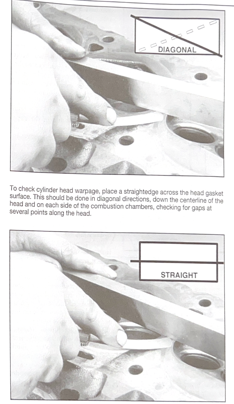
To check cylinder head warpage, place a straightedge across the head gasket surface. This should be done in a diagonal directions, down the centerline of the head and on each side of the combustion chamgers, checking for gaps at several points along the head.
The valves should be carefully inspected and cleaned. Hard carbon deposits can be removed from the valve head with a wire buffing wheel or glass bead blaster. Do not glass beed the valve stems.
The following are conditions which would require a valve to be replaced: cupped heads, evidence of necking (stretching and narrowing of the stem neck just above the head), pitting, burning, cracks, worn keeper grooves, too narrow a margin on the valve head or a worn or bent stem.
Stem diameter should be measured with a micrometer and compared to specifications. Measure the valve in a worn area and compare that to an unworn area of the stem below the keeper groove. Some valve stems are ground with about 0.001-in. (0.025mm) taper. Stems on these vavles are smaller at the combustion chamber end. Carefully check the keeper grooves for wear, too.
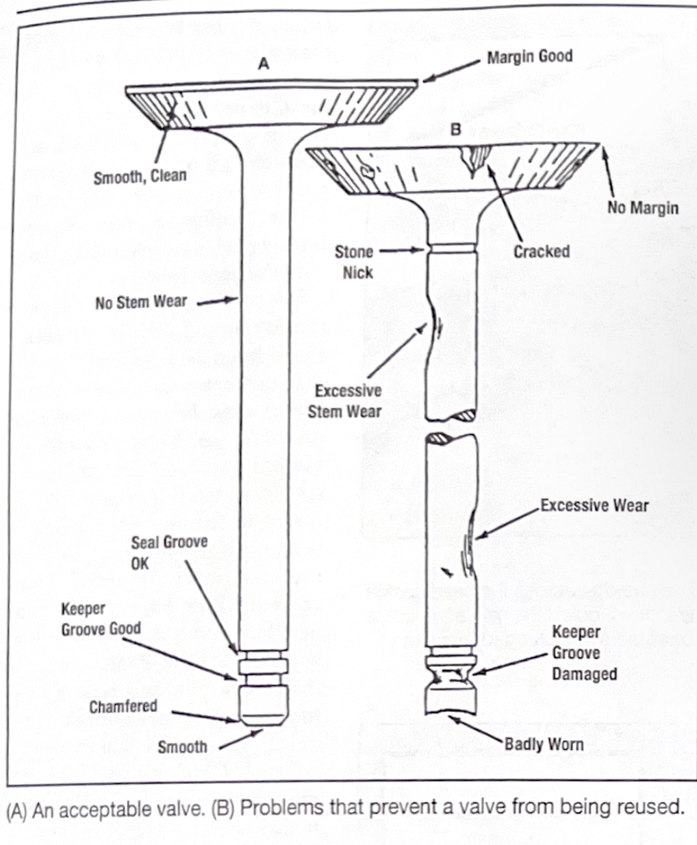
(A) An acceptable valve. (B) Problems that prevent a valve from being reused.
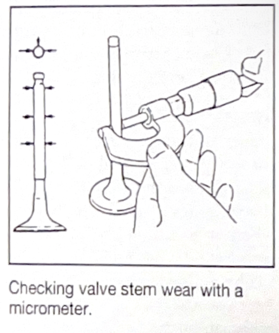
Checking valve stem wear with a micrometer.
Every head will show a certain amount of valve guide wear. Severe wear can indicate inadequate lubrication,problems with valve geometry, and/or wrong valve stem-to-guide clearance (too much or too little).
Inadequate lubricaion can result from oil starvation in the upper valvetrain, from low oil pressure or an obsructed oil passage.Inadequate guide lubrication can also be caused by using the wrong type of valve seal or using a positive seal in combination with an original equipment O-ring seal. Insufficient lubrication results in stem scuffing, rapid stem and guide wear, and valve sticking. Ultimately, the valve will fail due to poor seating and resultant overheating.
Valve geometry problems include incorrect installed valve height, out-of-square springs, and misaligned rocker arms (which push the valve sideways every time it opens). The resulting uneven guide wear leaves an egg-shapped hole. This leads to increased stem-to-guide clearance, poor valve seating, and premature valve failure.
A certain amount of clearance between the guide and valve steam is necessary so taht oil cal lubricate the stem and guide, and to allow for thermal expansion of the valve stem. Exhaust valves require more clearance than intake valve because they operate in higher temperatures and expand more. But the stem-to-guide cleance must also be tight enough to control oil consuption and to prevent exhaust gases from going up the stem and damaging the valve seal and spring. Varnish and carbon deposits can also build up on stems through the valve stems.
The type of guide also influences the amount of clearance needed. Bronze guides are said to be able to handle about half the clearance specified for cast iron guides or integral guides, with less tendency to seize. A knurled guide, one with oil retention grooves, or a bronze threaded liner, provides better lubrication than a smooth guide. Consequently, clearances for these types of guides can be kept closer to the low side of the listed tolerance. As extra assurance against sticking, do not go tighter than the specified minimum valve stem-to-guide clearance.
The design of the engine's valve guide seal is also a factor to consider when determining clearances. Comparaed to deflector O-ring or umbrella type valve sealves, positive valve seals reduce the amount of oil that reaches the valve stem. A guide with a deflector/O-ring valve seal may need somewhat tighter clearances thatn one with a positive valve seal to control oil consumption.
Guide clearance can be checked after cleaning the valve stem and guide with solvent and a brush to remove all gum and varnish. Insert the valve into its guide and hold it at its normal opening height. Rock it from side to side (in the same direction that the rocker arm would push on it) while checking play with a dial indicator. The amount of actual clearance is one halft of the TIR (Total Indicator Reading).
When valve to stem-to-guide cleance exeeds the specified limits, measure the valve stem with a micrometer to see if it si worn excessively. The I.D (Inside Diamater) of the guide can be measured with a split-ball guage and micrometer, a go/no-go guage, or a special valve guide dial indicator. A guide will typically sho the most wear at the ends and the least wear in the middle. This is called bellmouth wear.
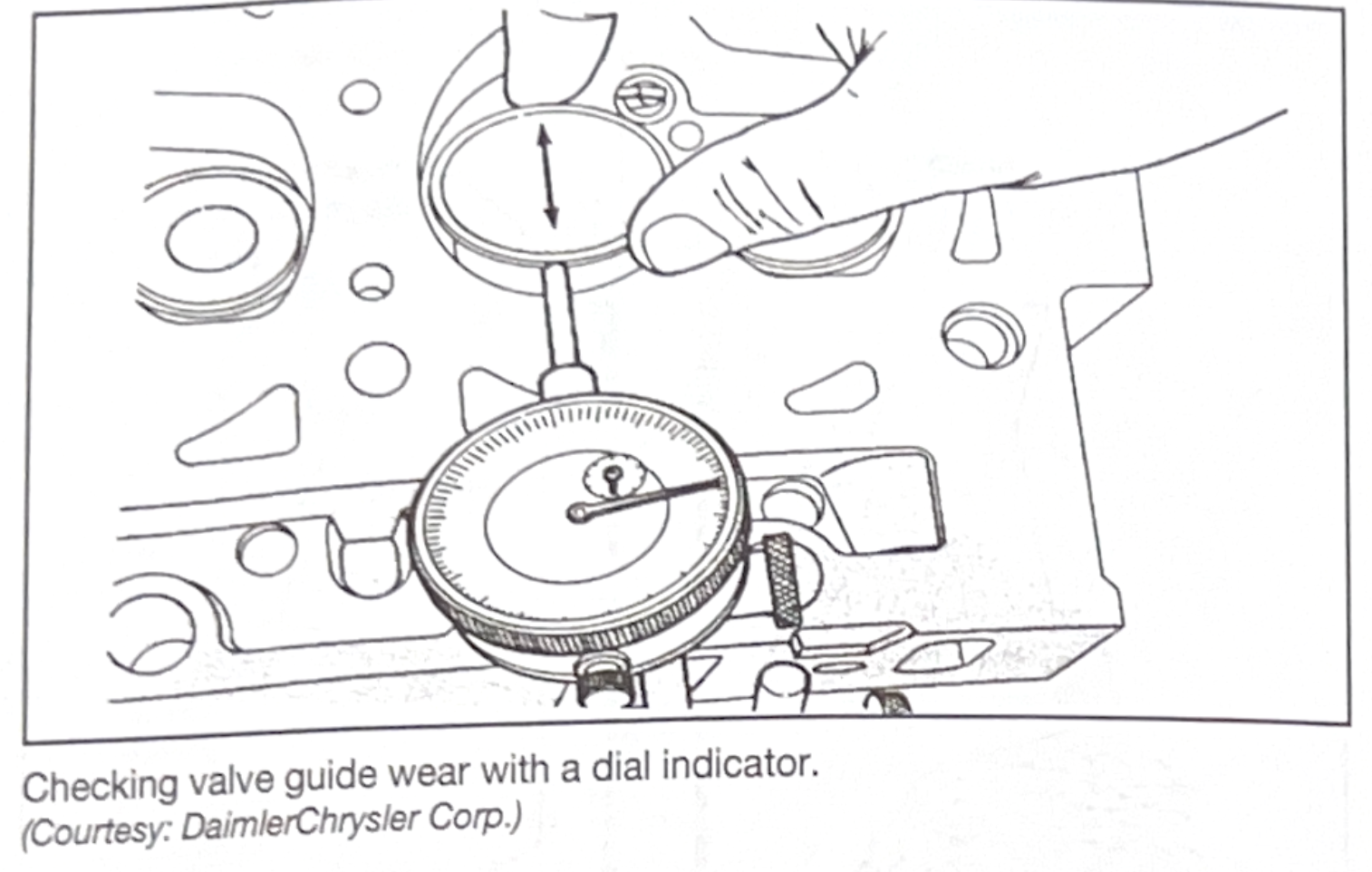
Checking valve guide wear with a dial indicator.
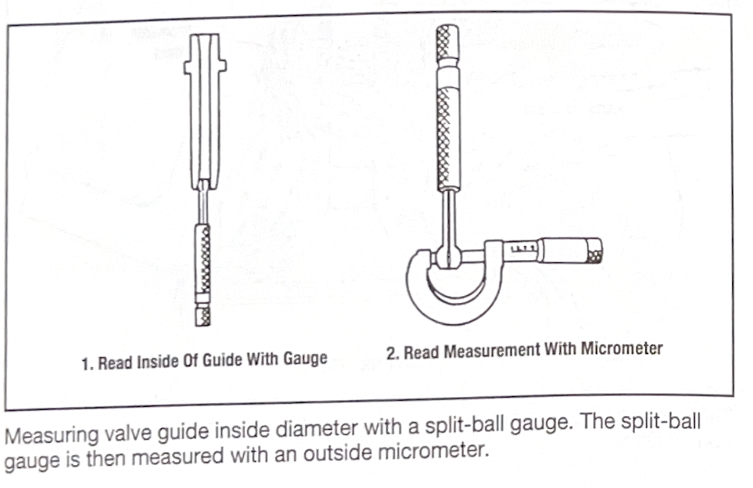
Measuring valve guide inside diameter with a split-ball guage. The split-ball guage is then measured with an outside micrometer.
Thoroughly clean and visually inspect the valve springs. Do not reuse a valve spring that has shiny ends or is shiny between the coils. These are indications of a weak spring. Also do not reuse a spring that is rusted, nicked or has deep scratches. Such flaws focus stress and can cause the spring to break.
Check the valve spring for tension, squareness and height. Start by checking the free-standing (relaxed) height of the springs (also called the spring free length). Individual spring height should be withing 1/16-in. (1.587mm) of the original equipment manufacturer's specification. Line all of them up and position a straight edge on top of them. Any spring that is 1/16-in (1.587mm) or more short than than the rest should be replaced. Short springs are often found where exhaust guide clearance has been excessive. Excessive heat from the exhaust weakens the spring. Keep in mind that some cylinder heads use rotators on just the exhaust valves. If the machined spring seats on the cylinder head are all the same height, the exhaust springs will be shorter than the intakees to allow for the thickness of the rotator. In this case the free-standing height of the exhaust and intake springs should be checked separately.
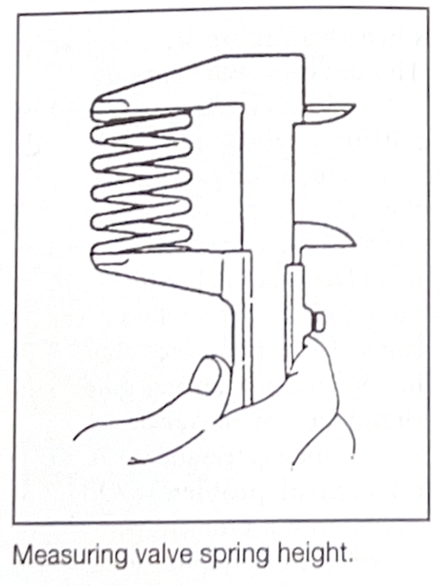
Measuring valve spring height.
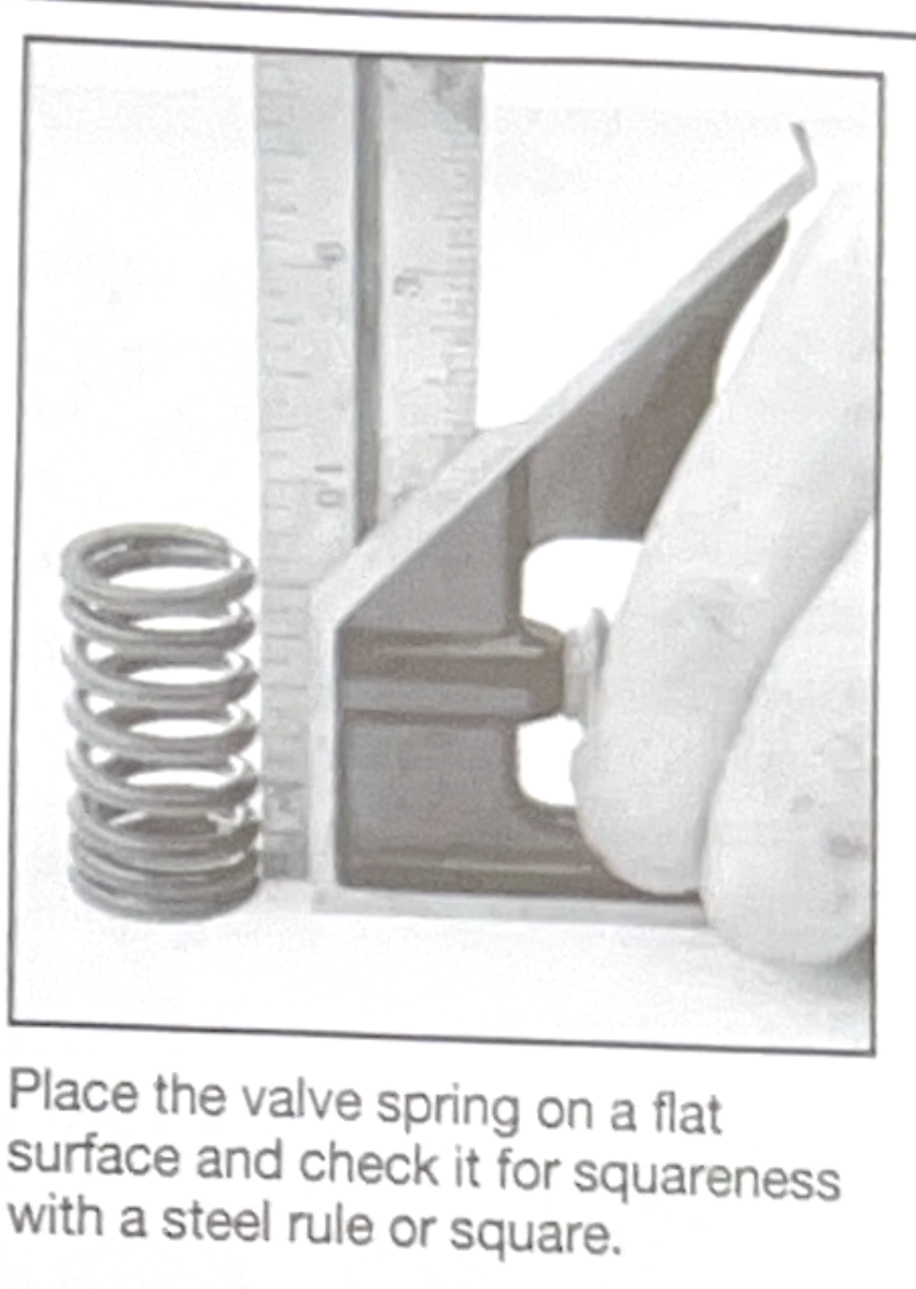
Place the valve pring on a flat surface and check it for squareness with a steel rule or square.
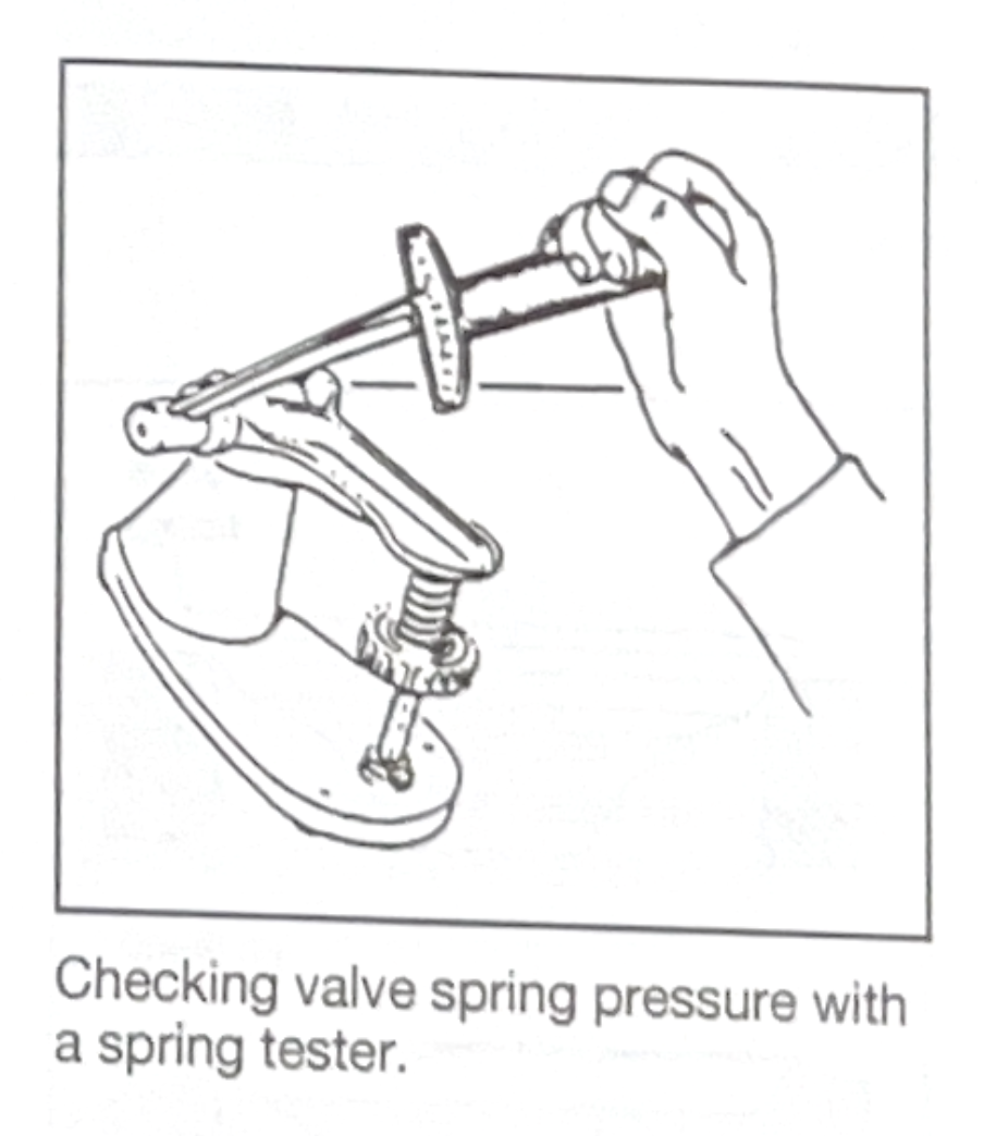
Checking valve spring pressure with a spring tester
Carefully check the keepers, valve spring retainers, and if equipped, rotators and studs for wear and damage. Many experts recommend that spring retainers and keepers be replaced whenever new valves and/or springs are installed, otherwise the retainers and keepers should be reused if they pass visual inspection. Make sure that rotators turn freely by hand without any grinding noise.
Worn or damaged press-fit rocker studs can be removed using a stud extractor or with a nut and a stack of washers. Oversized studs can be used for replacement if the stud hole is damaged or the hole can be tapped for the installation of a threaded stud. If the stud goes into a water jacket, be sure to use sealant when installing the new sud. When pressing in a new stud, make sure it is installed to the correct height.
Visually inspect the camshaft bores in the cylinder head for wear and damage. The camshaft bore I.D. can be checked using a dial bore guage or a telescoping guage and outside micrometer and compared with specifications. Bore alignment can be checked using a straightedge and feeler guage. If the bores are damaged or the I.D. and/or alignment are not withing specification, on some applications the cam bores can be machined to accept a cam with oversized journals. Otherwise the cylinder head must be replaced.
Visually inspect the condition of the hydraulic lash adjuster bores or cam follower bores, as required. Check the fit of each lash adjuster or cam follower in its respective bore.
The valve face and valve stem tip should be reground to a new finish on a valve refacing machine. Many manufacturers specify that the valve be ground to an interference angle of 1/2 to one degree. For example, if the seat is ground to a 45 degrees angle, the valve face would be ground to 44 or 44.6 degrees. Use of an interference angle improves valve seating and helps prevent carbon build-up. Always refer to the manufacturer's specifications for the proper valve face angle and dress the grinding wheel on the valve refacing machine before grinding the valve.
Clamp the valve in the refacing machine chuck and position the valve face just in front of the grinding wheel. Adjust the chuck feed so that when the valve face is moved back and forth, the grinding wheel will clear the valve stem. Start the machine and observe the valve head. If the valve head appears to wobble as the valve rotates, the valve is bent and must be replaced.
Move the valve back-and-forth while gradually feeding the valve towards the grinding wheel, until light contact is made. Grind the valve while maintaining light contact until the valve face is smooth. To avoid overheating the valve, make sure the coolant nozzle is directed at the valve while while grinding. Grind only what is necessary. Grinding more off of the valve fave leaves a narrower margin on the top of the valve head. The minimum limit of margin thickness for exhaust valve is usually 1/32-in. (0.794mm) above the valve face. A sharp edge can cause detonation and valve burning. Some OE (Original Equipment) larger intake valves have a narrower margin. Refer to manufacturer's specifications or compare an old valve to a new one when in doubt.
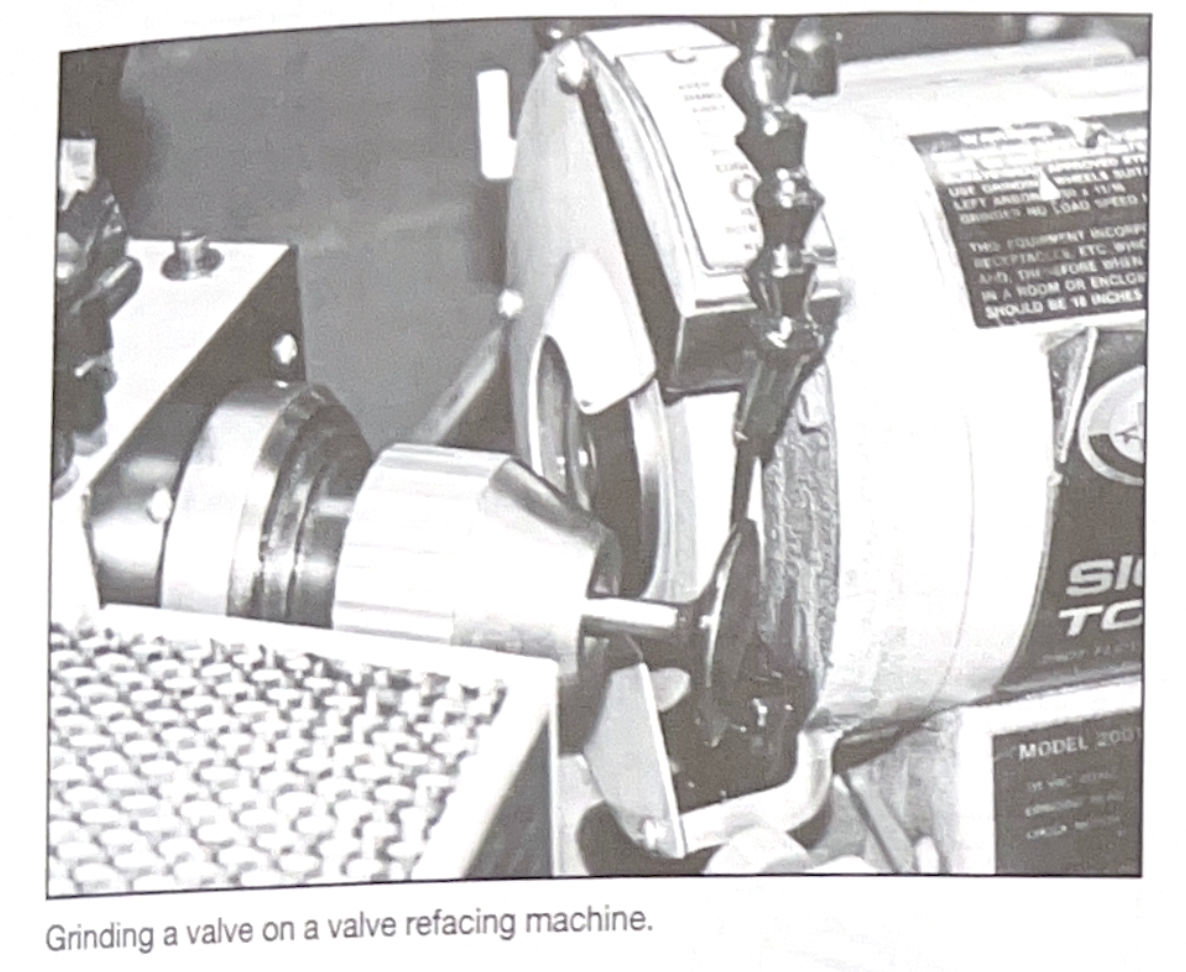
Grinding a valve ona valve refacing machine.
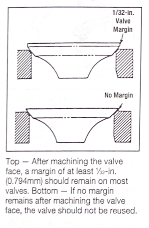
Top - After machining the valve face, a margin of at least 1/32-in. (0.794mm) should remain on most valves. Bottom - if no margin remains after machining the valve face, the valve should not be reused.
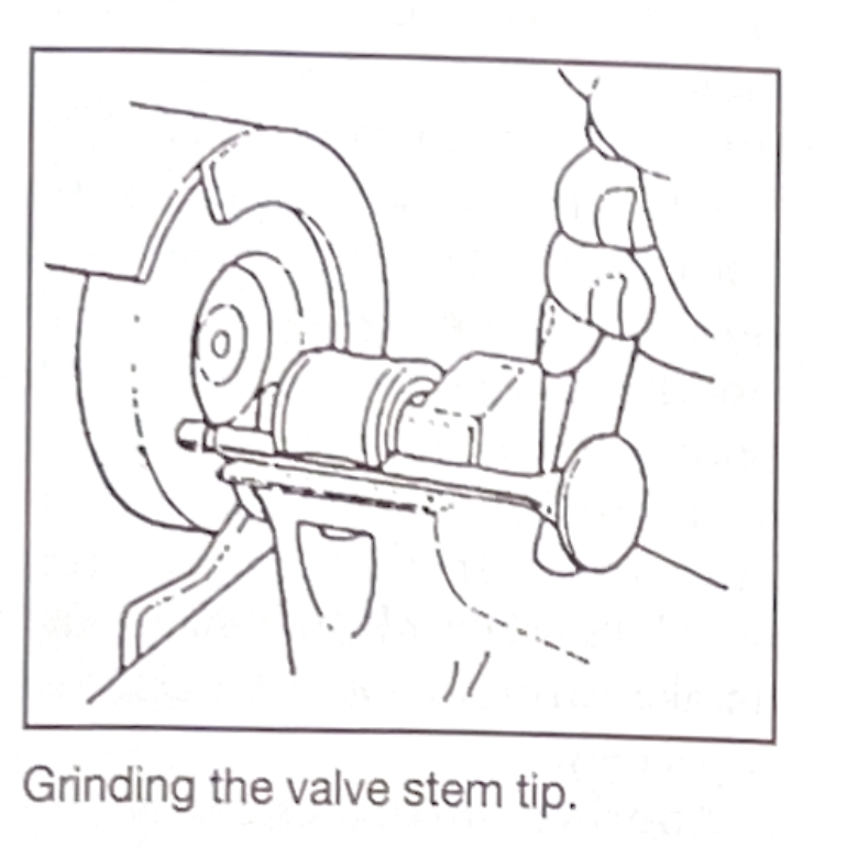
Grinding the valve stem tip.
Options for repairing worn valve guides include knurling, replacement, installing guide liners, and reaming to oversize and using valves with oversized stems.
Checking the amount of wear in the guides is the most important step to determine whether or not they can be knurled. If the guide is worn excessively, knurling may not restore the guide. Knurling decreased the guide I.D. more in the center (unworn area) than at its ends.
The knurling process consists of running a special wheel tool or ridged arbor through the guide. This leaves behind a spiral groove with raised metal reduces the I.D. of the guide. Next, the guide is finished by reaming to its finished size.
Knurling is self-aligning, so the centering of the guide with respect to the valve seat is not lost. Knurling also allows the original valves to be reused. The other primary benefit if knurling is improved oil control, compared to a smooth guide bore. The stem-to-guide clearance for a knurled guide can be as close as 0.0007-in. (0.0178mm). When guides are knurled and clearances are tight, however, positive valves seals are not recommended.
Replacement guides is done in both aluminum and cast iron heads. In cast iron heads, guides are often integral and a hole must be bored in the old guide to accept a pressed-in replacement guide.
To replace valve guides in aluminum heads, the heads must be heated to facilitate removal and installation without damaging the head. The guides are then usually driven out with a suitable driver and air hammer. The replacement guides are chilled and lubricated prior to installation. Most wet guides are tapered and require sealer to prevent leaks.
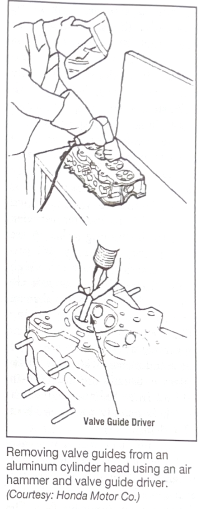
Removing the valve guides from an aluminum cylinder head using an air hammer and valve guide driver. (courtesy: Honda Motor Co.)
Thin tubes called thinwall valve guide liners are often installed to restore worn guides. This repair technique provides the benefits of a bronze guide surface (better lubricity, longer wear, and the ability to handle tighter clearances). Liners can be installed in heads with either integgral or replaceable cast iron guides. The process is portable, fast, and sometimes less expensive than installing new guides.
When valves are replaces, less machining time is required. If valves are replaced with those with oversized stems, all that is necessary is to ream the guide to the proper oversize. Stem-to-guide clearance should be in accordance with the engine manufacturer's recommendations.
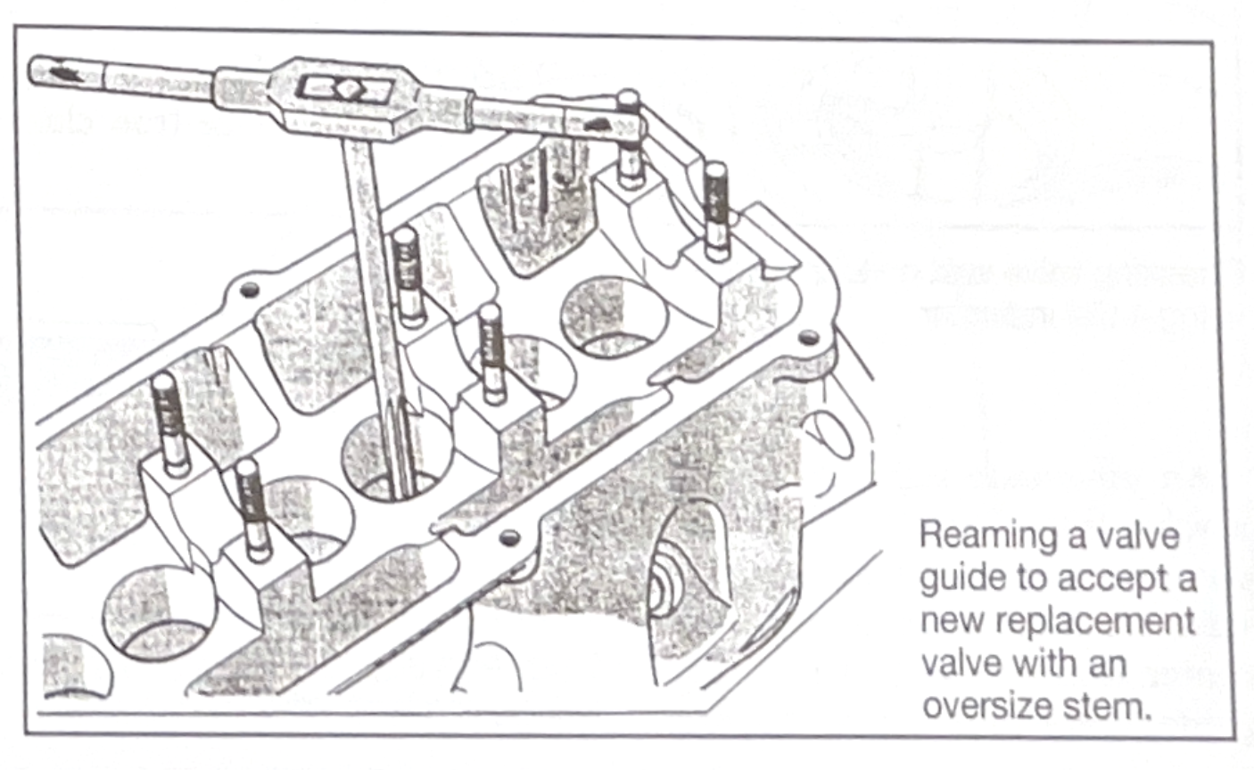
Reaming a valve guide to accept a new replacement valve with an oversize stem.
The guides must be reconditioned or replaced before cutting, grinding, or replacing vavle seats. All seat machining is done with a pilor that centers in the valve guide. If guide work is done after seat work, the guide and seat will no longer be aligned to each other.
A properly finished valve seat must meet several criteria. If a valve is to cool properly, it must have a concentric seat that is square with the guide. The seat-to-valve contact area must be of the correct width and positioned properly on the valve face.
A non-concentric seat will not allow the valve to make full contact. This results in a poor seal and loss of compression. Poor valve face-to-seat contact will also reduce heat transfer, causing the valve to run hot. This will eventually lead to premature failure. Check seat concentricity with a dial indicator. Concentricity should be within the 0.002-in. (o.05 mm).
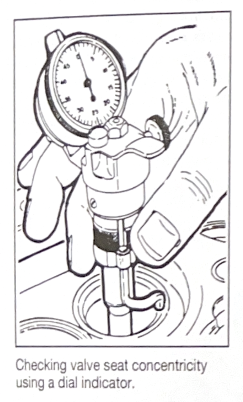
Checking a valve seat concentricity using a dial inidcator.
An off-square seat can prevent a valve from seating and holding compression. It can also lead to valve breakage. When a seat is off-center from the axis of the valve guide, every time the vavle closes it must flex to confrom to the seat. After thousands of such cycles, metal fatigue sets in and stress cracks develop in the valve. The provess is accelerated when valve rotators are used. Eventually the valve stem or head snaps. This often results in serious engine damage.
The width of the valve seat is important for good heat transfer, proper sealing and long valve life. A seat that is too narrow can suffer increased wear and will not be able to transfer sufficient heat to the cooling jacket. A seat that is too wide may not provide enough pressure for a tight seal. An excessively wide seat also tends to develop deposits that can prevent the valve from seating. This reduces heat transfer and lowers compression at idle. Recommended seat width for intake valves is usually around 1/16-in. (0.062-in.). Exhaust valve seat width is usually about 3/32-in. (0.093-in.).
The poinrt at which the valve and seat mate is also important. Ideally, the valve-to-seat contact area should be about one third of the way down the valve face. The top edge of the contact area should be about 1/64-in. - 1/32-in. below the margin of the valve. This leaves an area of the valve face between the margin and top of the seat contact area that overhangs into the combustion chamber.
When the area of contact is too hight on the valve face (too close to the margin), the valve is too far into the head. This increases installed height, reduces valve spring tension, upsets valvetrain geometry, and restricts free breathing. Another valve positioning problem is when the area of contact is too low on the face (too far from the margin). As the engine warms up and the valve expands, the contact point moves down the valve face away from the margin. The valve may lose partial contact with the seat, causing it to lose compression and run hot.
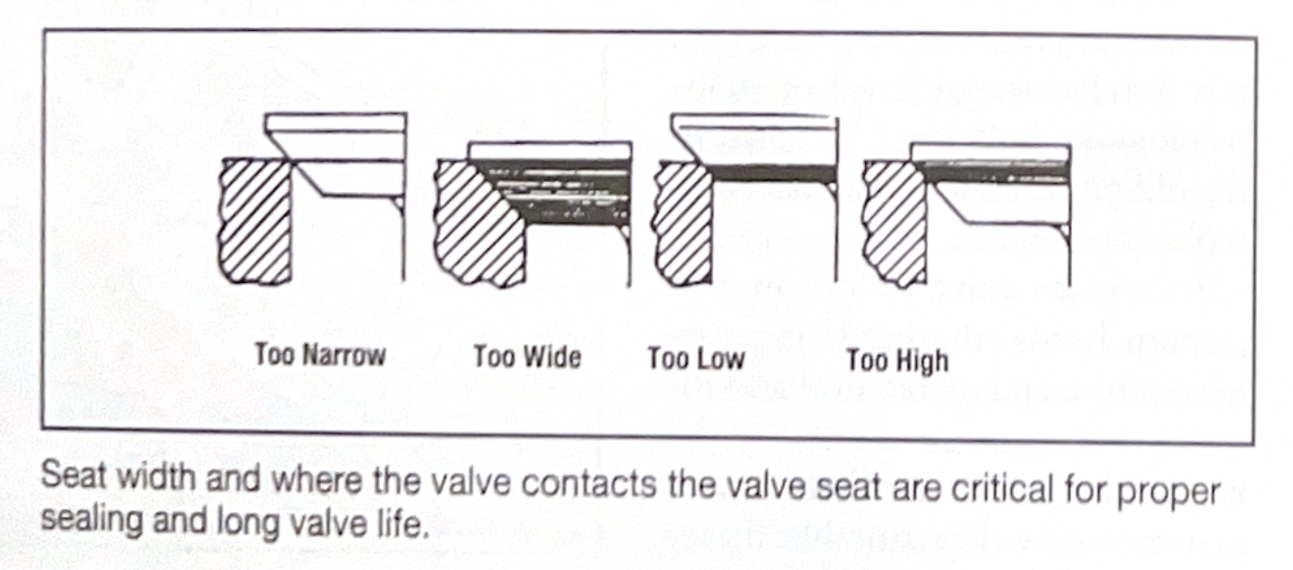
Seat width and where the valve contacts the valve seat are critical for proper sealing and long valve life.
Valve seats should be replaced if they are badly worn or ground too deep in the head. Replaceable inserts (typically used in aluminum heads) should also be replaced if they are cracked or loose in the head. Heads with integral seats can be machined to accept a replaceable insert.
Seats can be ground with a wet or dry stone, or cut with a carbide cutter. There are advantages to each method. Grinding requires at least three steps for each set and in the case of dry stones, produces abrasive dust. Stones must be properly dressed to maintain accuracy. Cutting is cleaner and faster, especially when all three angles are cut at once. Cutters are more expensive, however.
To grind at seat, select a wheel about 1/8-in. larger than the seat. The angle of the stone depends on the manufacturer's specifications. A typical seat face angle is 45 degrees, but occasionally 30 degrees is used (most often for intake valves). The grit of the stone depends upon the material the seat is made from. For best results and fast stock removal, use coarse stones on hard seats and a finer general purpose stone for cast iron seats.
Thread the stone onto the stone holder. Some stone holders have a ball bearing assembly inside and may be used with lifting spring.
Another type of stone holder has a brass bushing inside. A lifting spring cannot be used with this type.
Adjust the angle on the stone dressing stand to the correct setting. Dress the stone using a diamond nib, taking a small amount of material off of the stone. Attepting to remove too much from the stone at once will lift the stone and result in an uneven grinding surface. The diamond nib can also be undercut and removed from the dressing tool. Take quick strokes across the stone. Slow strokes can glaze the grinding stone (especially with finer grit stones).
Select the correct size pilot to insert into the valve guide. Slide the stone and stone holder (and lifting spring, if used) over the pilot. Grind the seat with a gentle circular motion. Be sure to be gentle and hold the stone holder in alignment to the pilot. Pushing the stone to the side can cause seat runout. If there is no lifting spring, lift the stone holder away from contact with the seat before it stops turning. This will give a smoother finish.
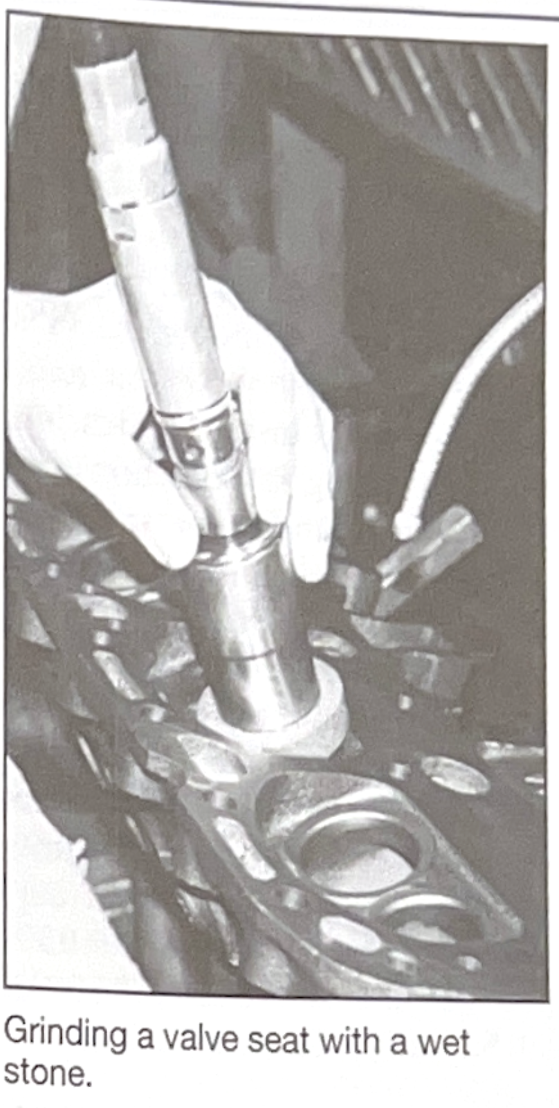
Grinding a valve seat with a wet stone.
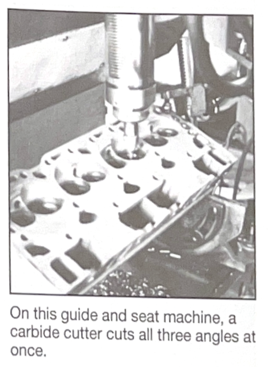
On this guide and seat machine, a carbide cutter cuts all three angles at once.
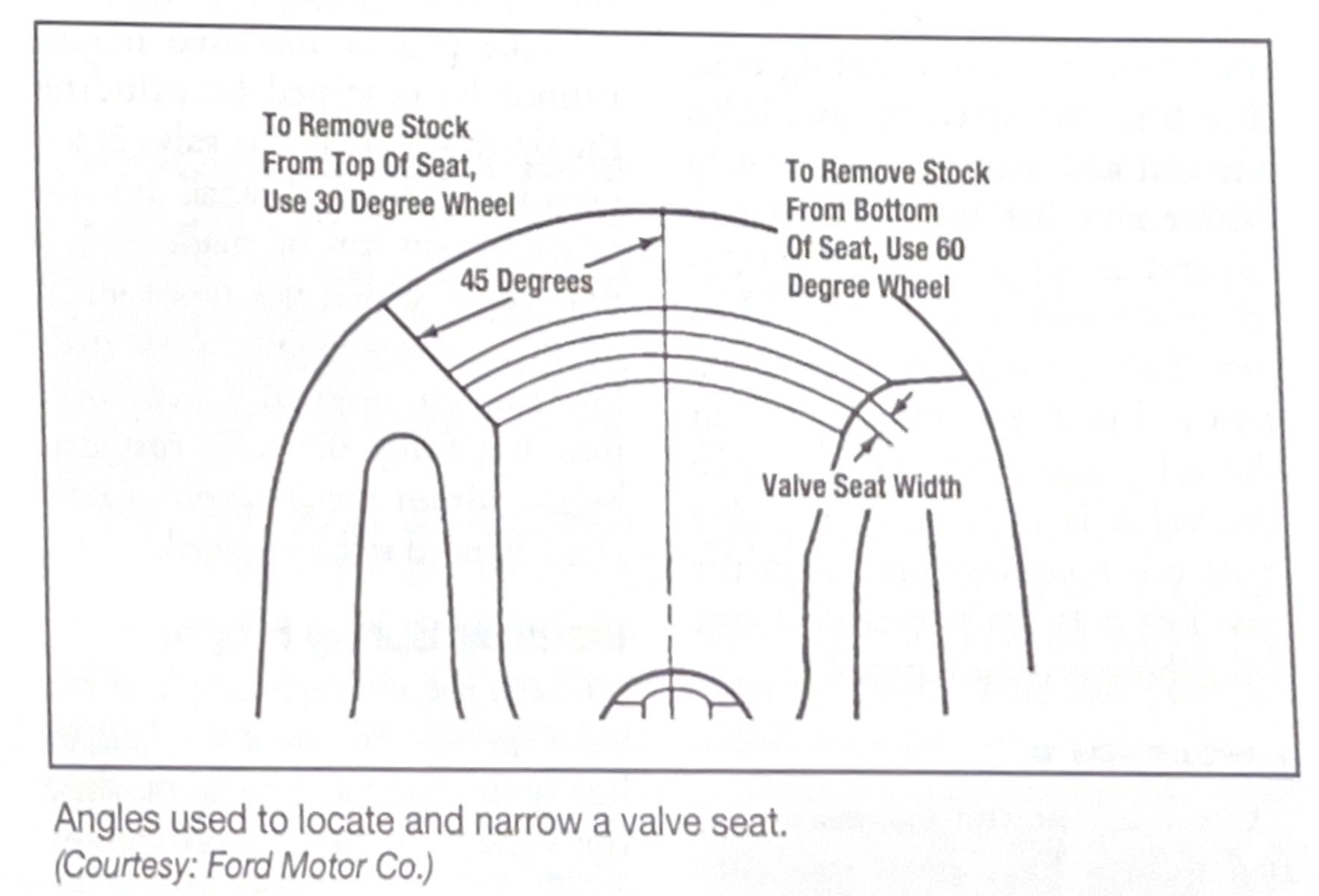
Angles used to locate and narrow a valve seat.
Once all of the valve, seats, and guides have been reconditioned, wash the head, valves, springs, retainers and keepers thoroughly in clean solvent to prepare for reassembly.
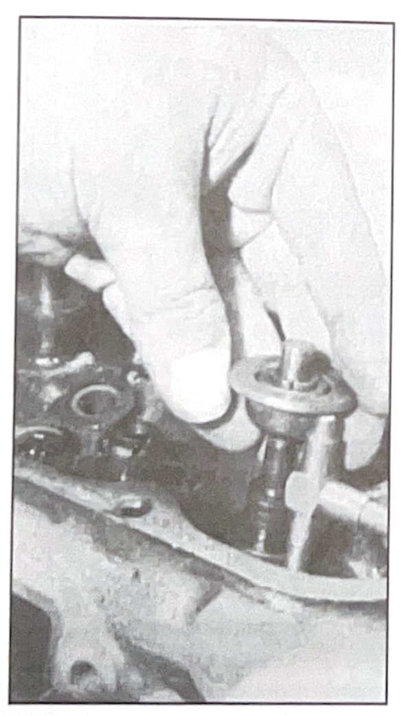
To determine if shimming is needed, a telescoping gauge is expanded between the valve spring seat and the underside of the valve spring retainer. The guage is then measured with an outside micrometer and the distance compared with the valve spring height specification.
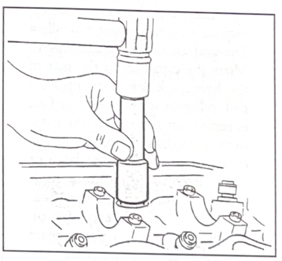
Installing positive valve stem seals.
Camshaft lobe lift and endplay can be checked while the cam is installed in the cylinder head or block.
To check lobe lift on an OHC engine, install a dial indicator so the indicator foot is on the camshaft lobe. Rotate the engine until the indicator foot is on the base circle of the camshaft lobe, then zero the indicator. Continue rotating the engine untile the indicator foot is on the high lift point of the cam lobe. Record the indicator reading. Repeat for each cam lobe and compre the readings with specifications. Replace the cam if any reading is below specification.
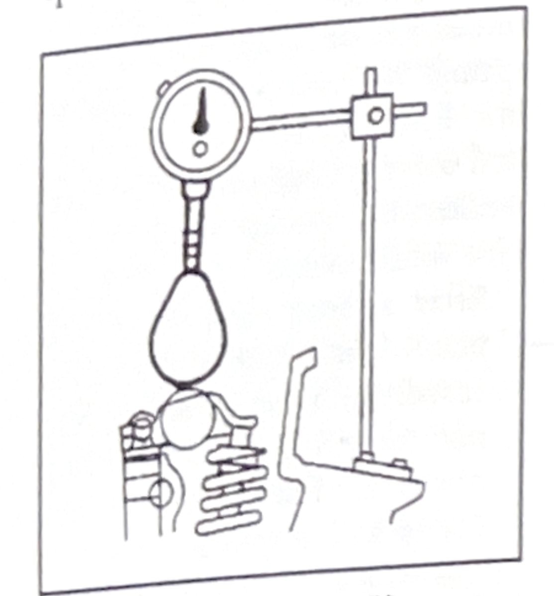
Measuring camshaft lobe lift on an OHC engine.
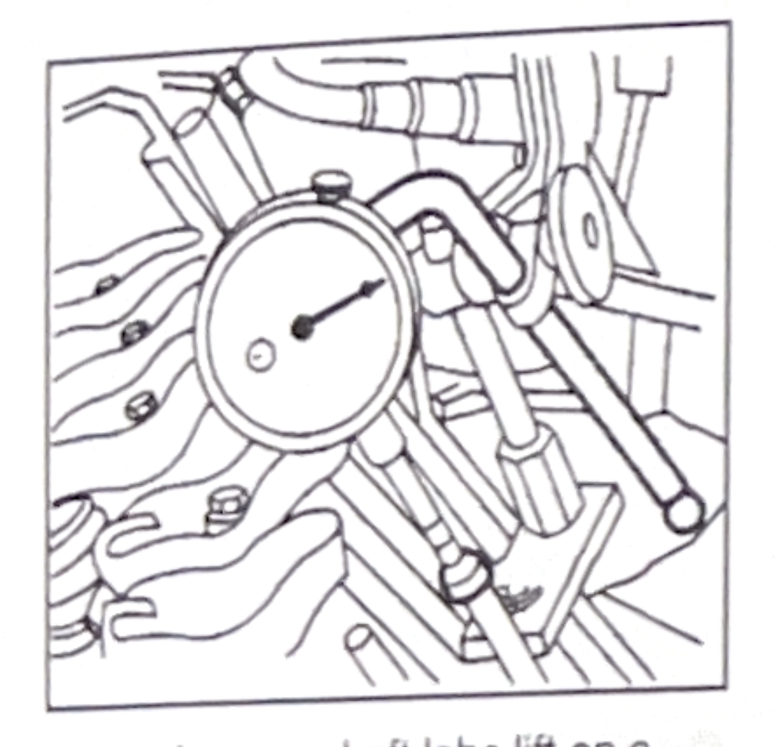
Measuring camshaft lobe lift on a psuhrod engine.
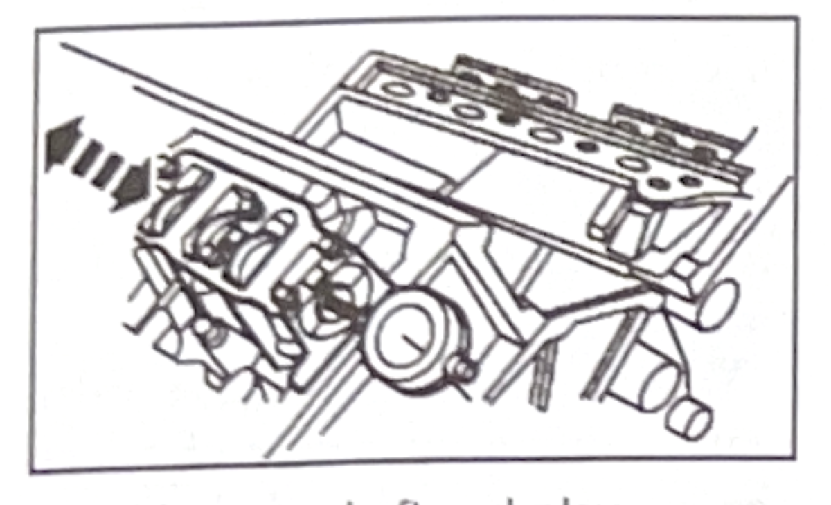
Checking camshaft end-play.
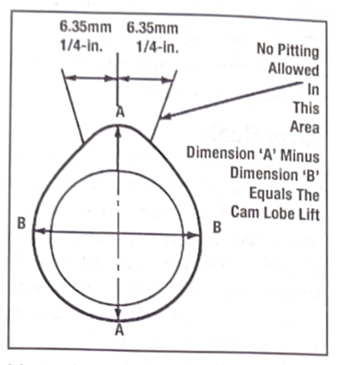
Measuring camshaft lobe wear. The difference between measurments 'A' and 'B' represent lobe lift.
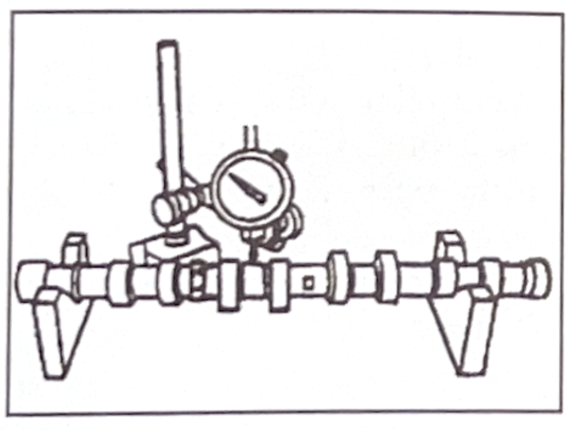
Checking camshaft runout.
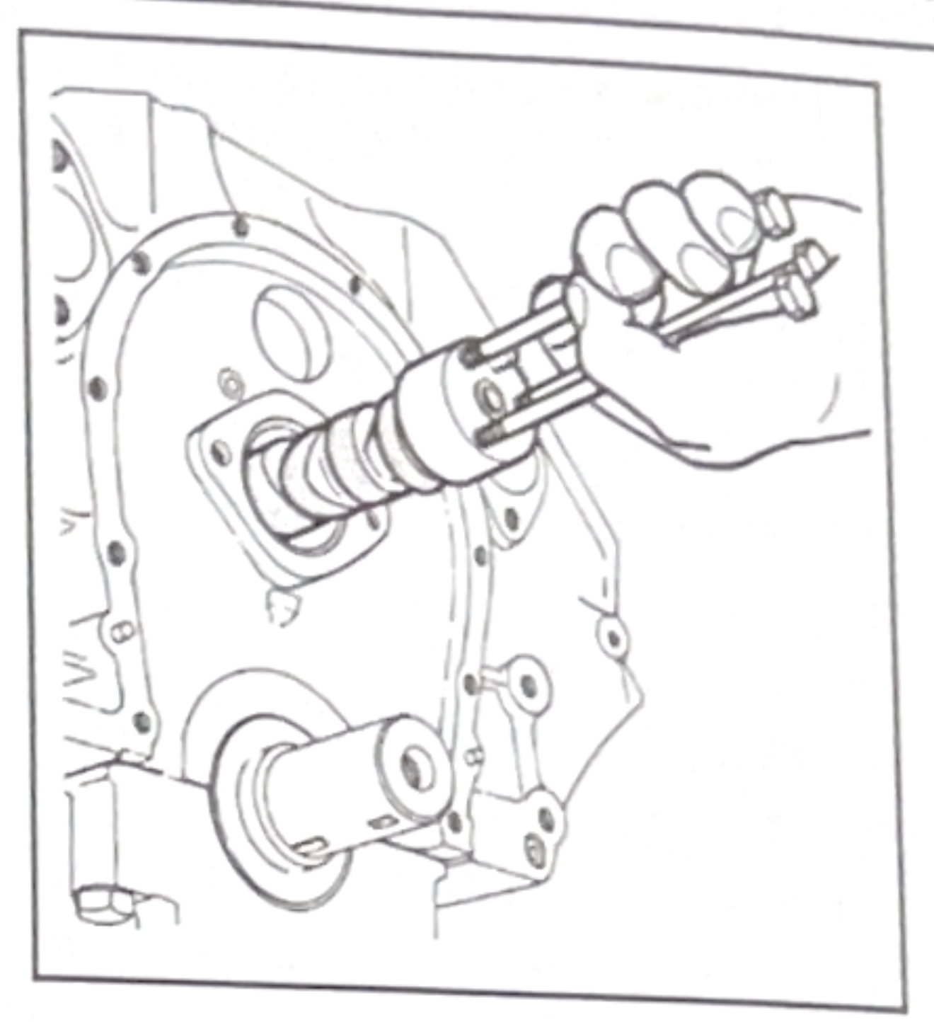
Extreme care should be used when installing the camshaft to avoid damaging the camshaft bearing.
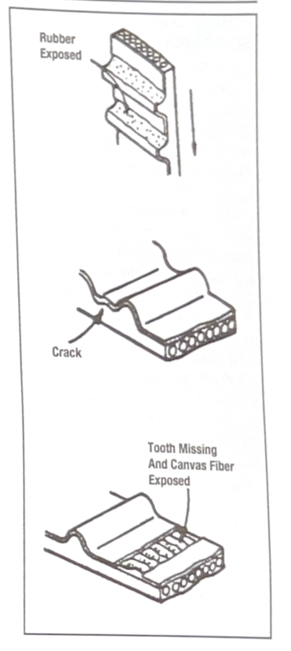
Look for these conditions when inspecting a timing belt.
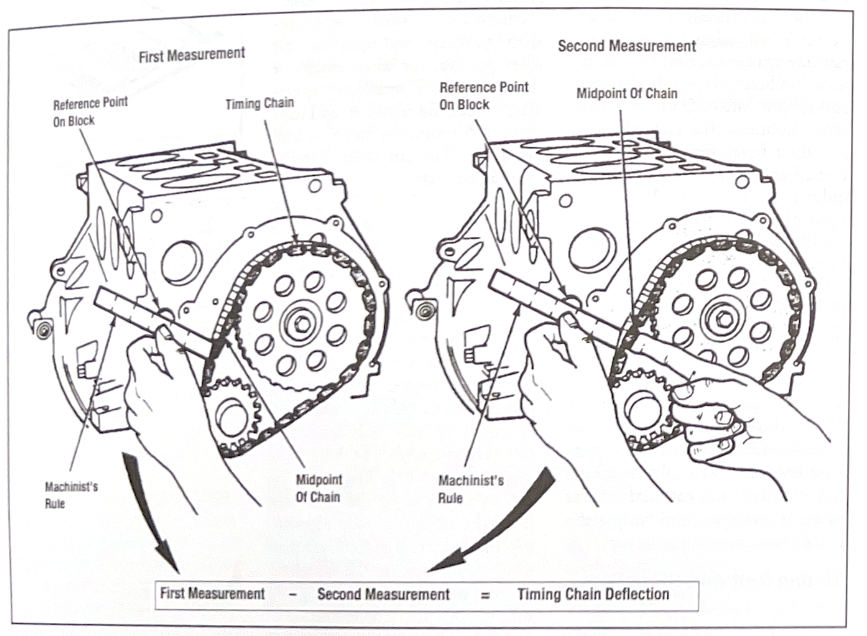
Measuring timing chain deflection.
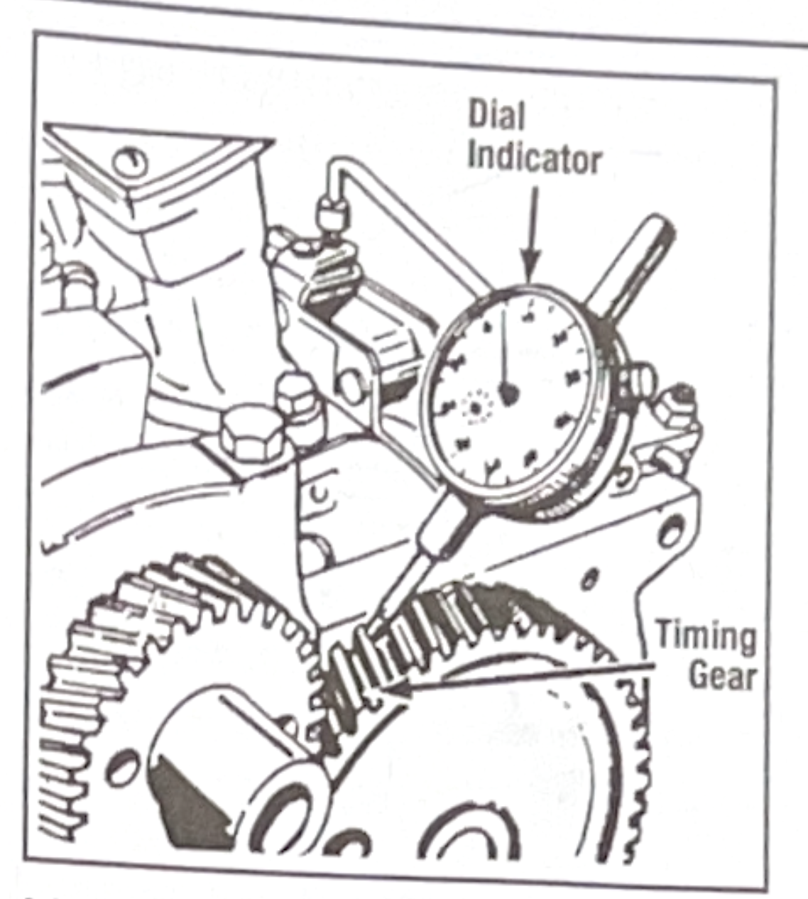
Measuring timing gear backlash.
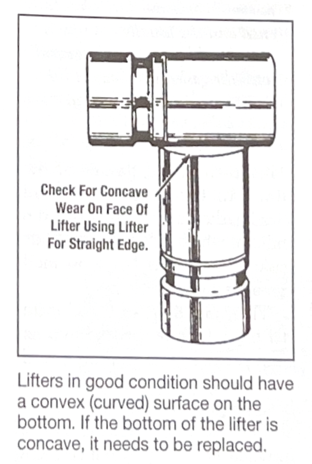
Lifters in good condition should have a convex (curved) surface on the bottom. If the bottom of the lifter is concave, it needs to be replaced.
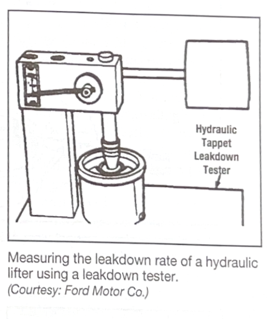
Measuring the leakdown rate of a hydraulic lifter using a leakdown tester.